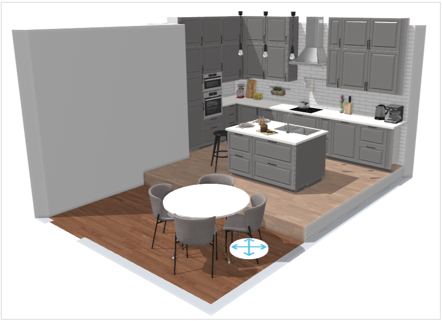
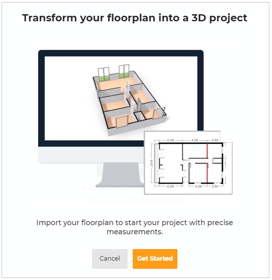
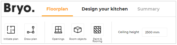
Floorplan
This section explains functionalities available in the Floorplan step that you can use for designing your floor plan.
The first step to design your kitchen is defining the shape of the kitchen room that is floor plan.
Following features in kitchen planner are useful to draw the floorplan of the kitchen.
Choose room shape
When you open the kitchen planner for the first time and enter your floorplan, the popup window appears to select your kitchen's room shape, as shown below:
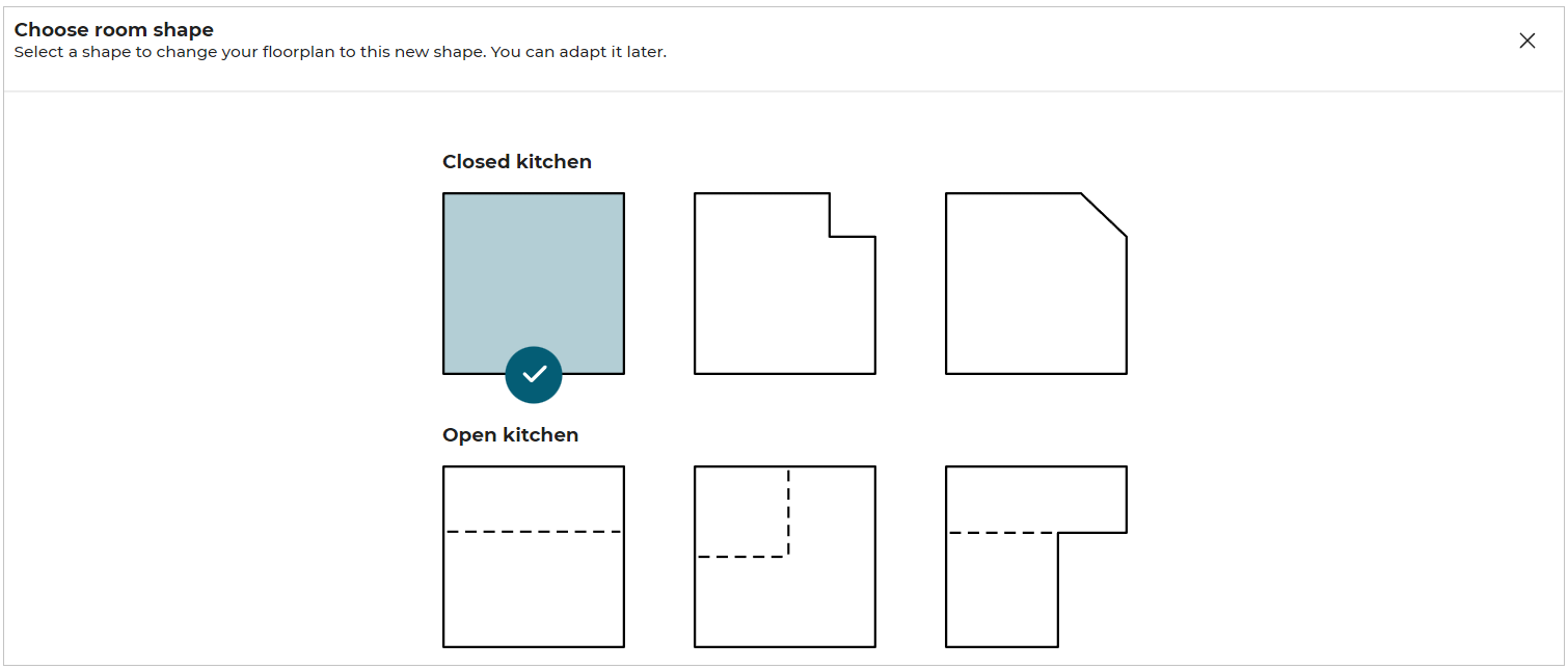 Choose the desired shape for your floorplan.
Functionalities in Floorplan
These features are accessible from the floorplan step, as illustrated below:
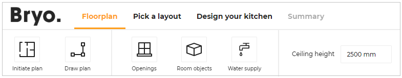
Initiate Plan: Used to initiate plan by changing the room shape or importing a Homebyme project.
Draw Plan: Adds walls, room separation, and manages sloped ceiling in the floorplan.
Openings: Adds openings to the kitchen like door, window, etc.
Room Objects: Adds room objects like columns, radiators or free shapes.
Water Supply: Selects the wall for water supply.
Ceiling Height: Modifies the height of the room wall by changing the value.
Initiate Plan
This section explains the steps to change the room shape, use a HomeByMe project or use a measuring code. This is the first step in kitchen planning.
Click Initiate plan to see the available options.

Features of Initiate Plan
Change Room Shape
To change the room shape, click the Change the room shape option.
Options for room shape appears, as shown below:
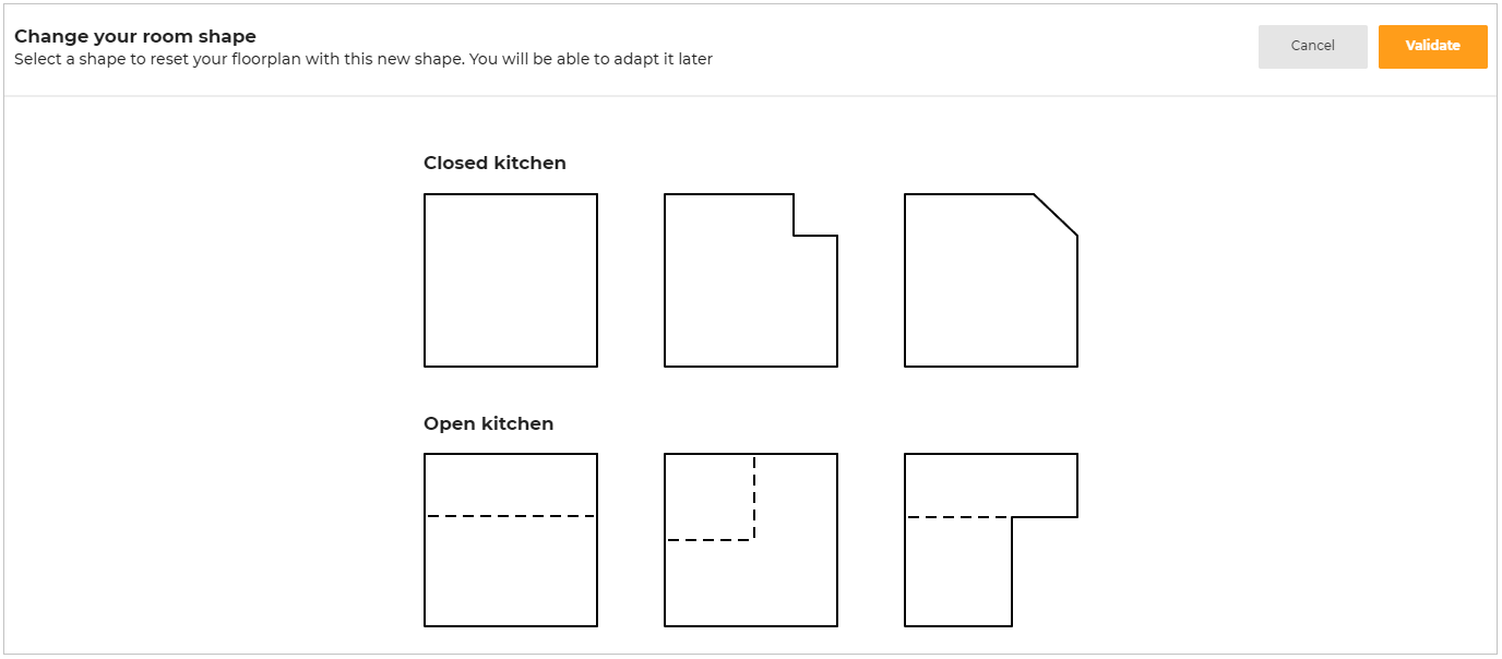
There are two types of room shapes available:
- Closed kitchen are the kitchens with closed rooms.
- Open kitchen are the kitchens with room separators in the rooms.
Select the room shape from the options available.
Click Validate to proceed with the shape.
Click Cancel to delete the selection and go to the previous shape.
Points to note:
- If a floorplan containing cabinets or appliances is modified using Change the room shape option, a notification confirming the overwrite of previous floorplan appears, as shown below:
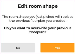
Click Yes to overwrite the previously created floorplan or click No to stop overwrite.
- If a floorplan with coverings is modified, and Change the room shape option is selected, the covering is applied to the changing room.
Using a HomeByMe Project
To import a copy of a HomeByMe project into the kitchen application, click Use a HomeByMe project option.
An onboarding page is displayed explaining the different steps to import your HomeByMe project to design your kitchen.
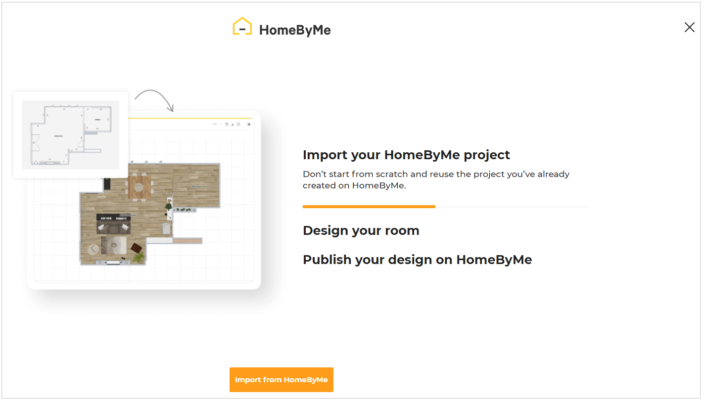
Click Import from HomeByMe option.
If the user has not already logged in to HomeByMe, a login page appears, as shown below:
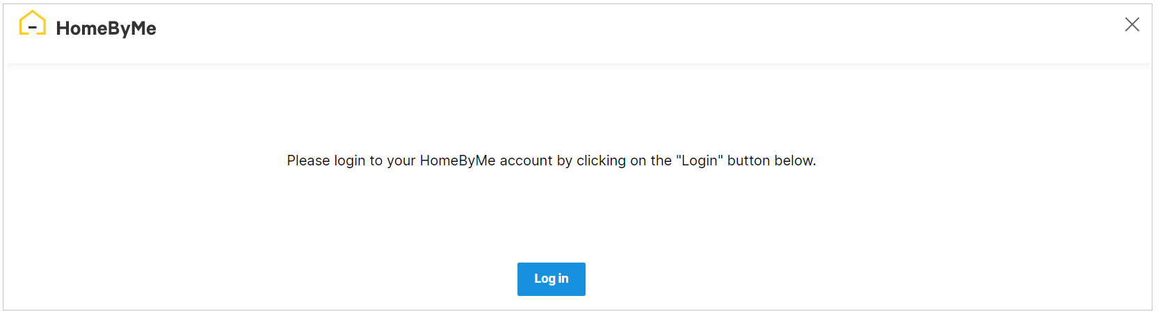
Click the Log in button.
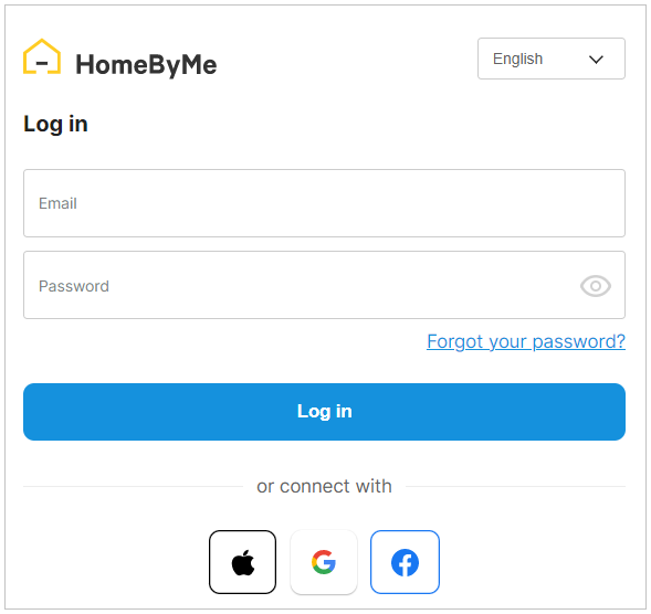
Enter the credentials and click the Log in button, or connect HomeByMe using Facebook/Google/Apple account.
After successful login, the HomeByMe connects and your projects in HomeByMe are displayed.
Case 1. If you have no projects in your HomeByMe account, the window with the message "You have no HomeByMe projects" appears, as shown below:
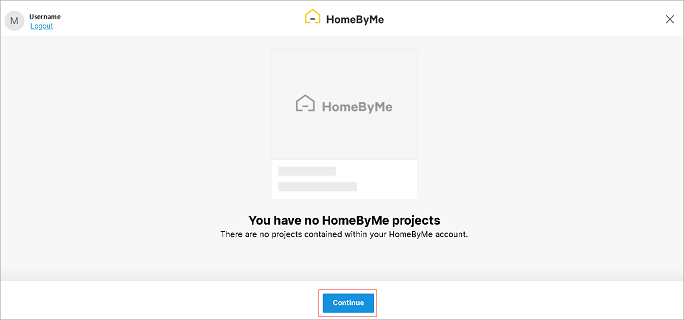
Click the Close button, you will be redirected to the Bryo application.
Case 2. If you have only one project in your HomeByMe account, the project selection step is skipped, and the available project is imported.
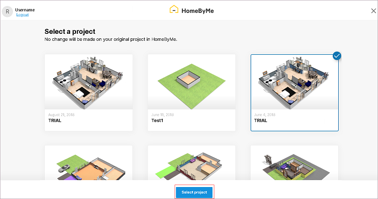
Case 3. If you have several projects in your HomeByMe account, select the project and click the Select project button to import it in the kitchen application, as shown below:
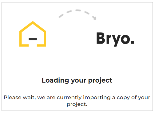
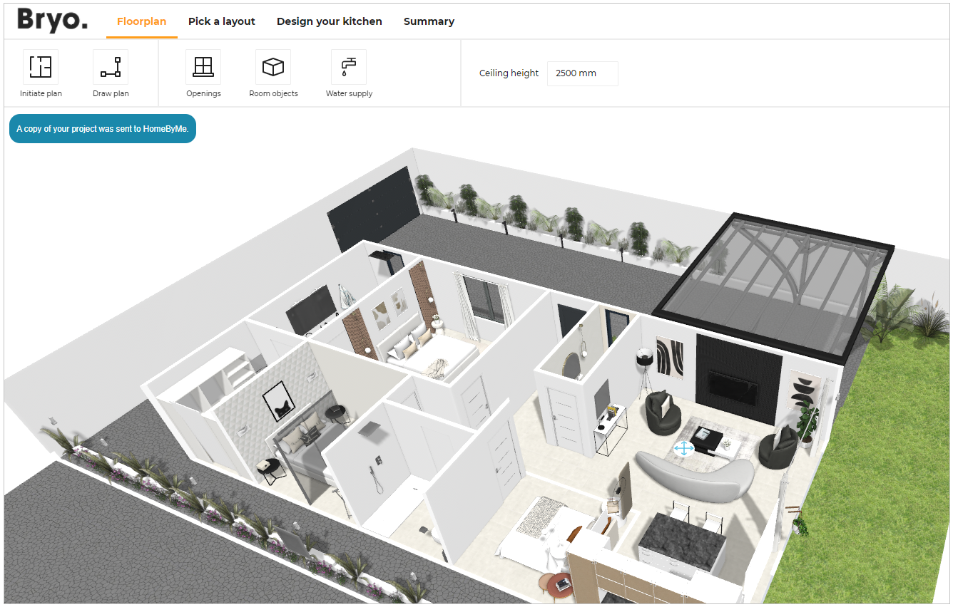
The integration begins, as shown below:
A copy of the HomeByMe project is imported in the Bryo application.
- If the selected project has multiple floors in it, a notification to select the floor appears, as shown below:
Select which floor you want to import in the Bryo application.
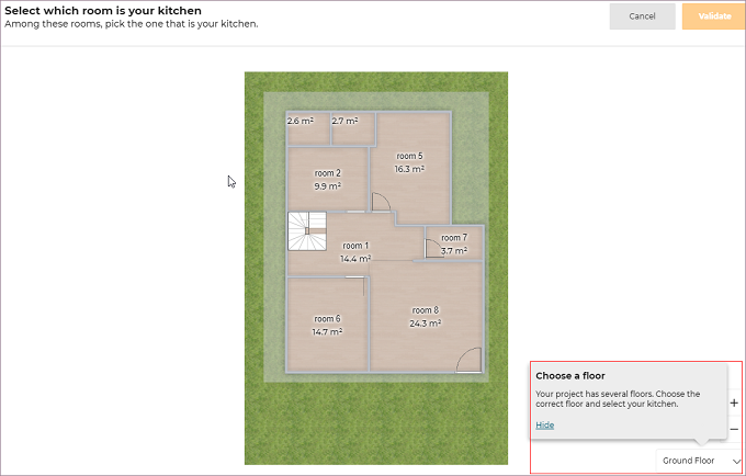
- If the selected project has multiple rooms in it, select which room is your kitchen, as shown below:
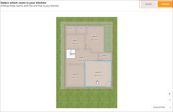
Select the room and click the Validate option.
A copy of the HomeByMe project is imported into the kitchen application, as shown below:
For further designing of the kitchen, please refer Pick a Layout, Design Your Kitchen, and Summary steps.
Importing the Measure Code
To import the measured code to the planner, click the Use a measure code option.
Select the required file from the folder.
A popup message to notify Your measurements have been imported appears, as shown below:
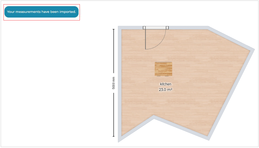
The Existing project has been updated accordingly and the kitchen products are not positioned after importing the measurement code.
You have to manually drag and drop the products to position them inside the kitchen.
To position, the products, select Design your kitchen step and drag and drop the products inside the kitchen.
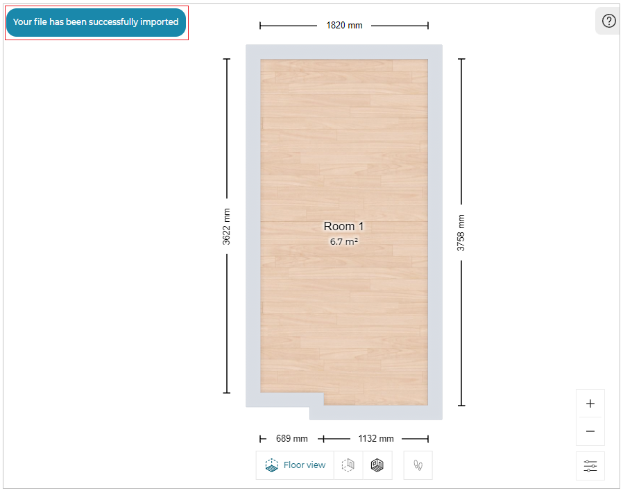
The original room shape is updated based on the measurement been imported.
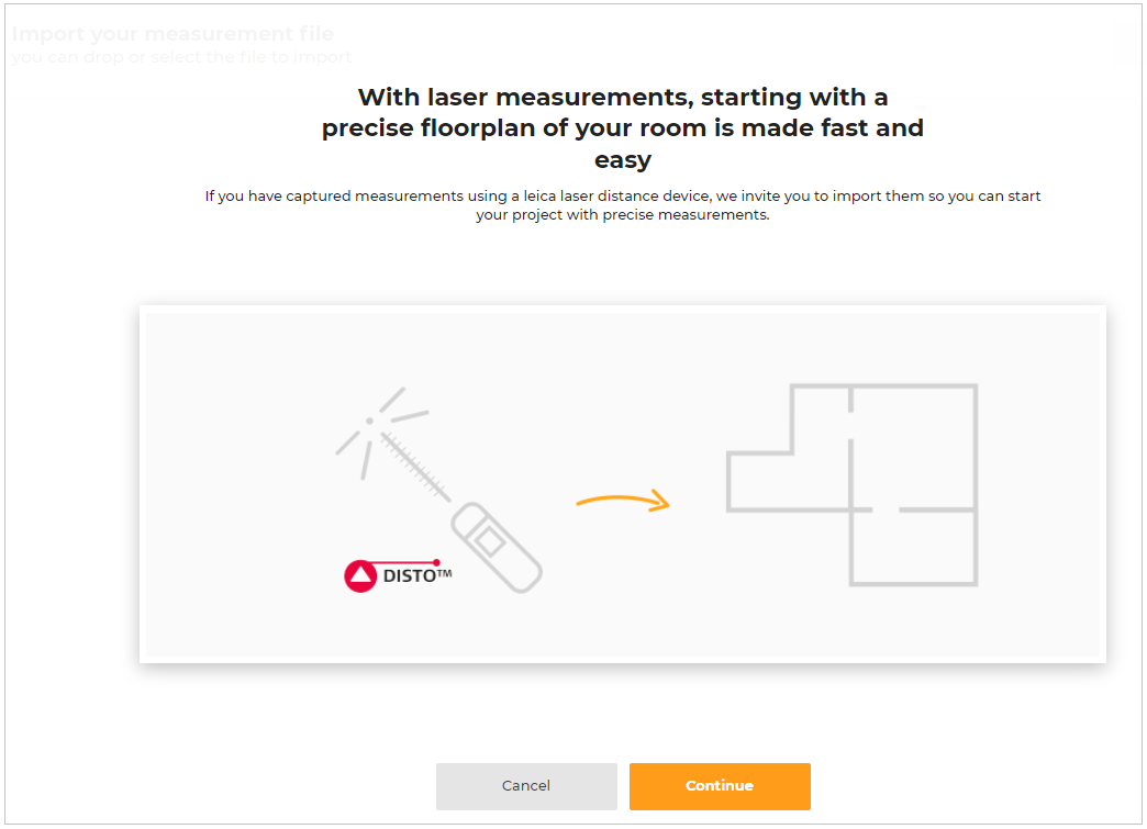
Importing Leica Laser measurements
⚙️ Set up: Application distribution parameter floorPlanImport.leicaMeasure 🔗.
The Import laser measurements option is available in the application when thefloorPlanImport.leicaMeasureis set to True. The default value is set as false in theimportOptions.
To import the file generated from Leica laser measure, click the Import laser measurements option.
The window to import the measurements using a Leica laser distance device appeared, as shown below:
Click the Continue button, the window to import the file appears, as shown below:
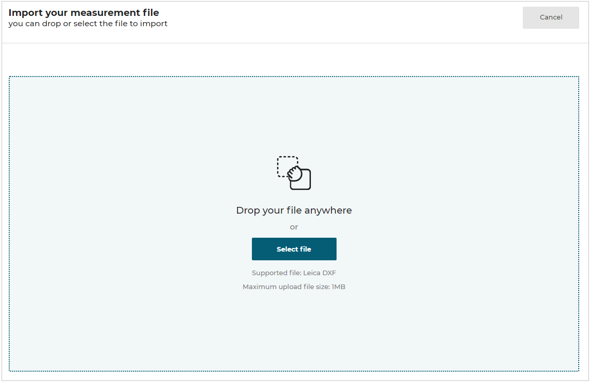
Select the required file from the folder.
A popup message to notify Your file has been successfully imported appears, as shown below:
- You can upload measurements in .dxf file format and the maximum file size supported is 1 MB.
- The modifications to the project (i.e. products, project name, and description) are lost.
Upload 2D floorplan
This section explains the steps to upload the 2D floorplan in the planner.
-
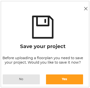
Click the Upload a 2D floorplan option, the window to save your project appears, as shown below:
-
Click the Yes button and enter the name and description of the project.
Select the Save button.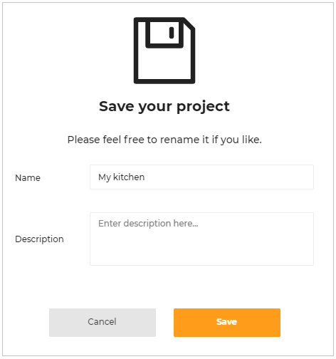
-
Click the Get started button to upload the floorplan.
-
Click the Select file option to upload the floorplan file from the folder.
Also, you can drag and drop the 2D plan file.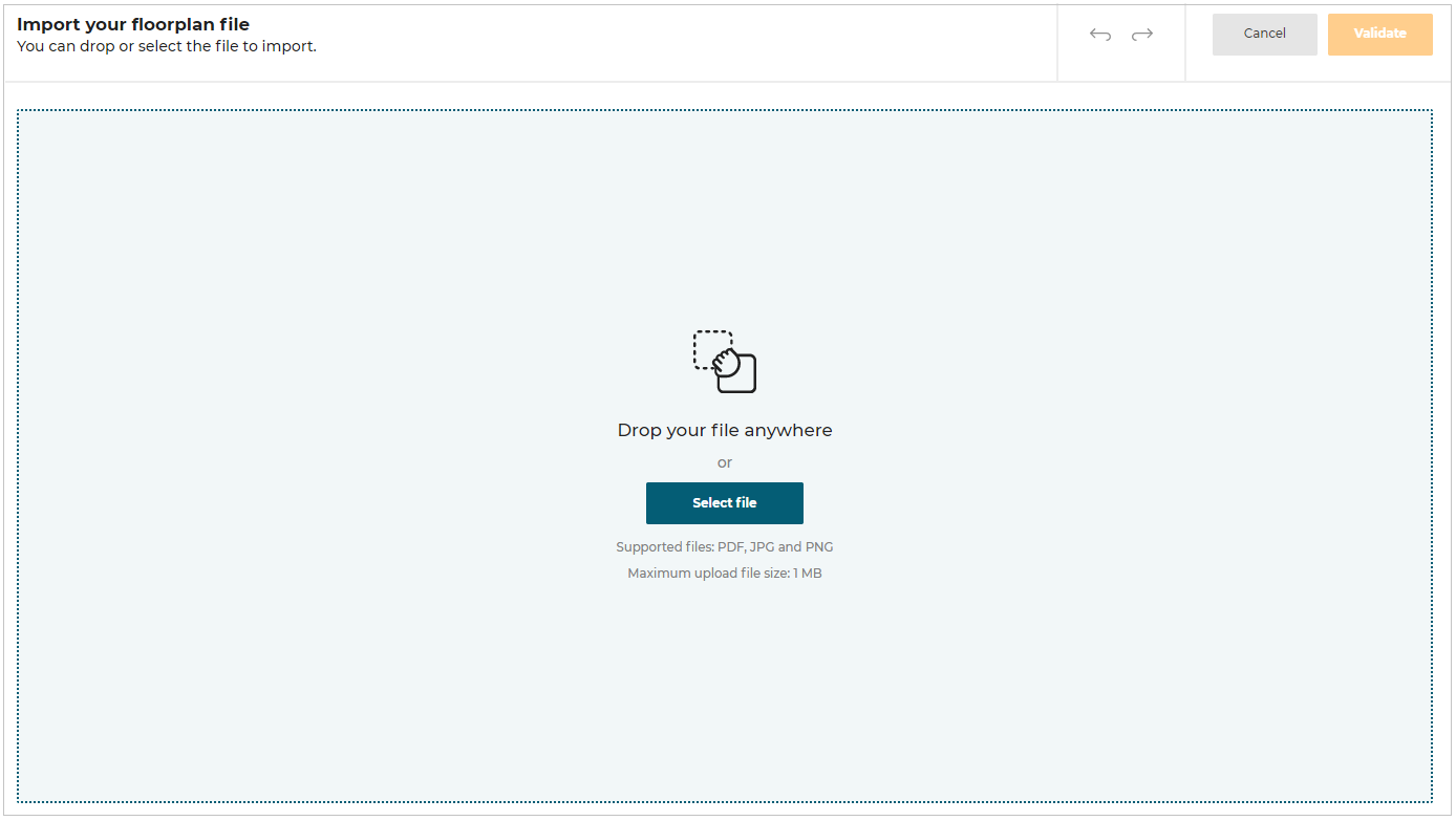
-
To upload image file:
Select .jpg or .png image format file from the folder, the file is uploaded as shown below: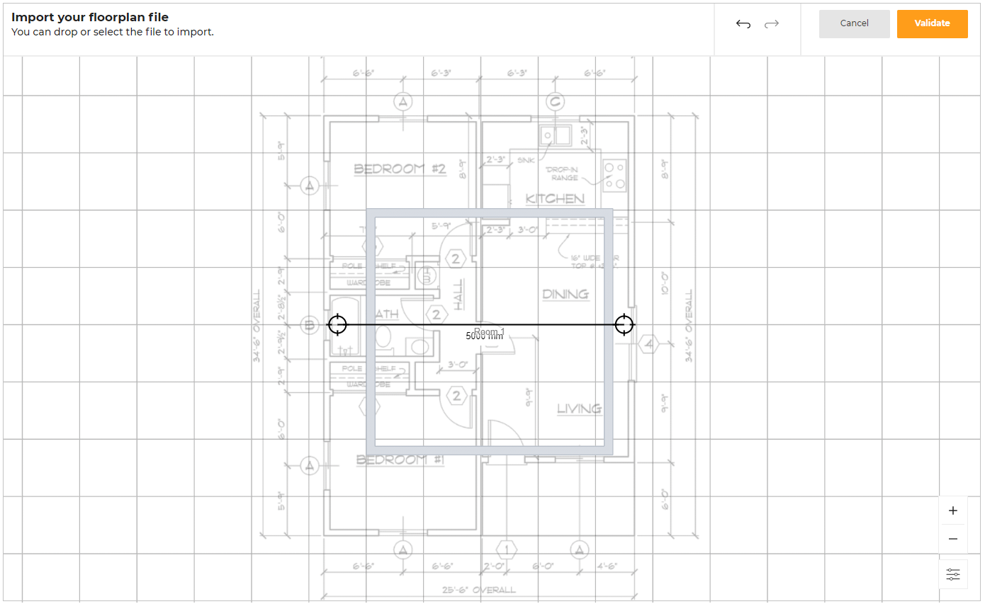
-
To upload PDF file:
You can upload a single-page PDF file or a multiple-page PDF file.Single page PDF file upload:
Select the PDF file from the folder.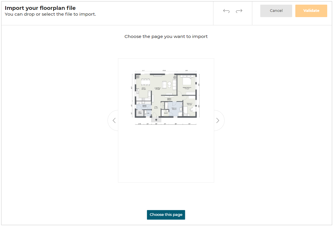
Multiple page PDF file upload:
Select the PDF file from the folder.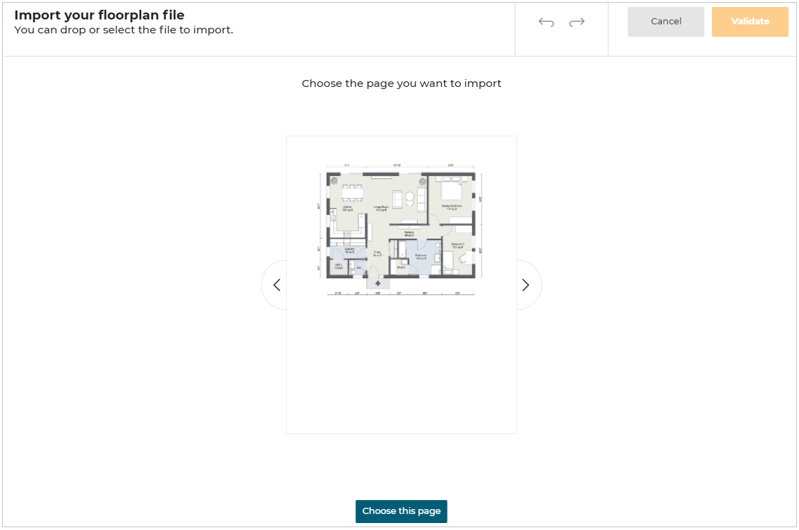
- You can preview the file by clicking on the Next/Previous arrow option.
Next/Previous arrow option activates only when the PDF file contains more than one page.
- Click the choose this page option to select the required page.
-
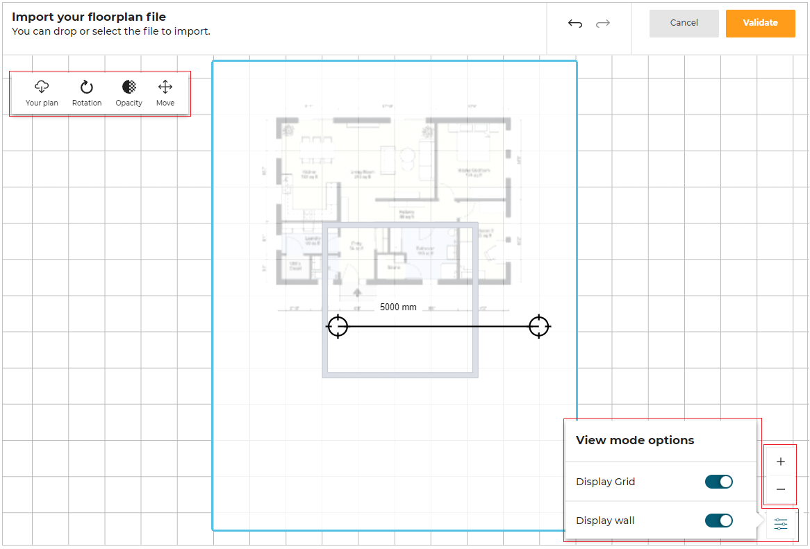
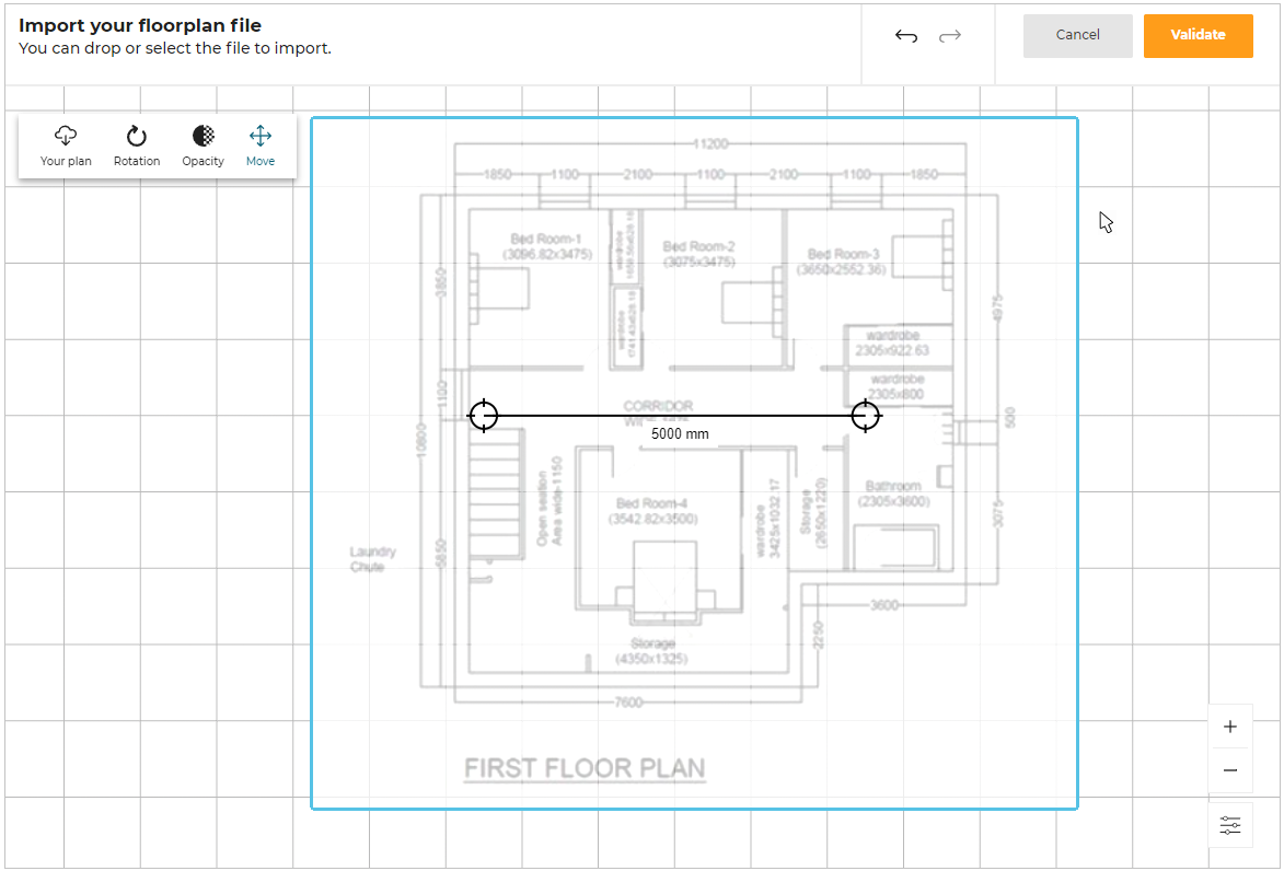
Plan Adjustment option:
For plan adjustment options, click on the uploaded flooplan.
The options displayed, as shown below:
-
Click the Your plan option.
The options to Delete/Change the uploaded plan are displayed, as shown below:
To Delete the plan, select the Delete button and click the Yes option.

To change the plan, select the Change button.
The Import your floorplan file window is displayed.
-
Click the Rotation option.
The Floorplan rotation option to rotate the plan is displayed, as shown below:
-
Click the Opacity option.
The Floorplan opacity option to change the opacity of the floorplan is displayed, as shown below:
-
Click the Move option to adjust the position of the plan.
As soon as the position is adjusted, click the Move option again or click outside the plan to fix the position of the plan, as shown below:
- Click the icon
 for View mode options.
 - Click the Display grid option toggle button to hide/display grid lines of the planner.
- Click the Display wall option toggle button to hide/display walls in the plan.
- Click the
 to zoom in on the plan.
 - Click the
 to zoom out the plan.
-
You can drag the endpoints of the scale to adjust it according to the 2D plan.
Also, you can enter the required distance value between the two points. -
Click the Validate button.
The 2D plan is uploaded to the planner.
You can upload 2D plan in .pdf, .jpg, and .png file formats.
Draw Plan
This section explains the steps to add a wall, room separator, or sloped ceiling.
Click the Draw plan option, its features appears, as shown below:

Features of Draw Plan
Adding Walls
To add a wall, click Add a wall option.
The Add a wall editor appears, as shown below:
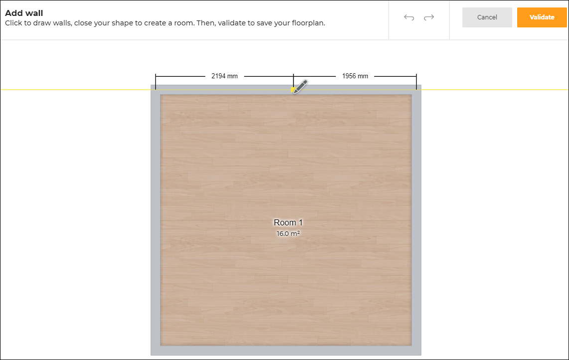
Multiple walls and rooms can be created according to your requirements, as shown below:
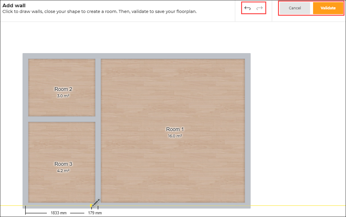
Click the Validate button, to proceed with the design.
Click the Cancel button, to delete the design modification.
To undo the previous action, click the Undo icon.
To redo an action, click the Redo icon.
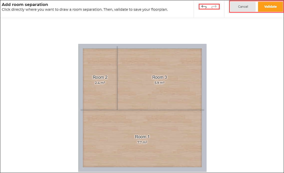
Adding Room Separations
To add a room separation, click Add a room separation option.
The Add room separation editor appears, as shown below:
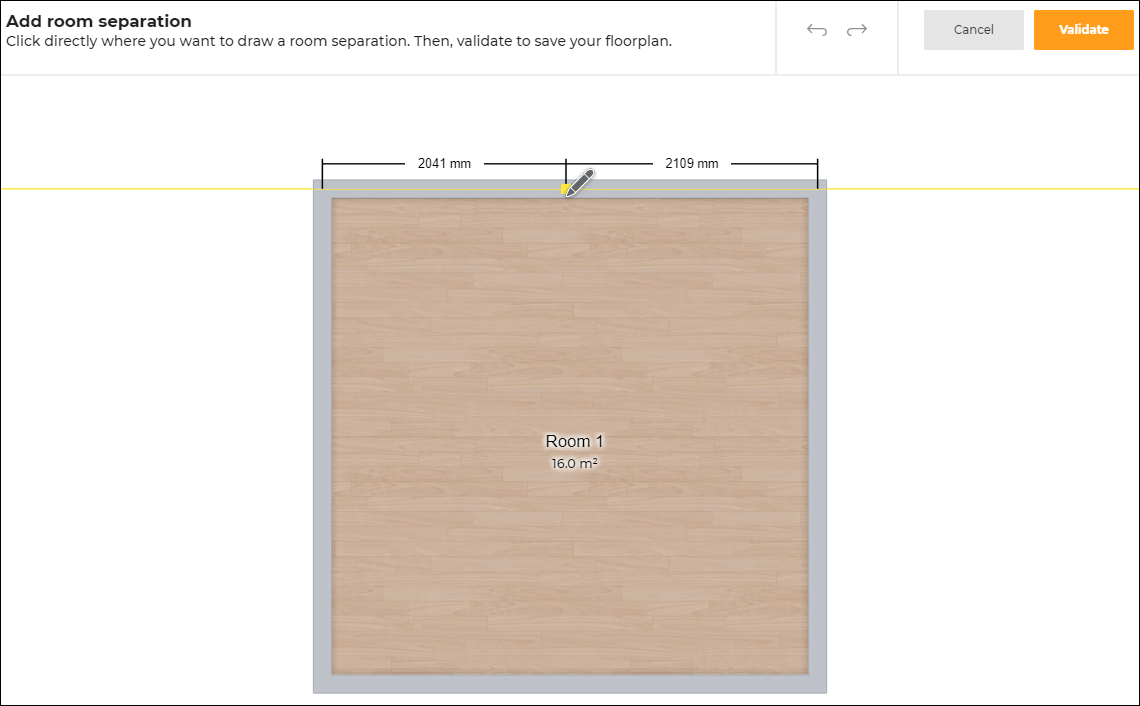
You can create multiple room separation, as shown below:
Points to note:
- If a room has no room separator but has discontinuous walls in the room, then the entire room will be considered as one, as shown below:
Therefore, the cabinets are added to the entire room, irrespective of the discontinuous walls. - To create two separate rooms with discontinuous walls, add a room separator between them. In such cases, the cabinets are added to the room where the avatar is present.
- A room separator cannot end in the middle of a room. If so, a dashed line representing the room separator is displayed.
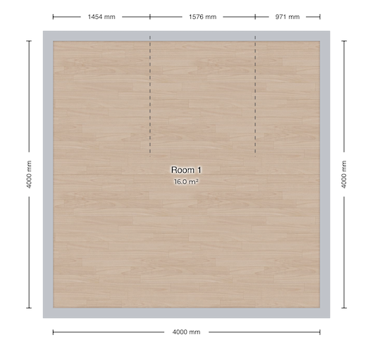
This dashed line represents the room separator but it is not fully separating the room.
You can add the room separator between two walls or between two room separators.
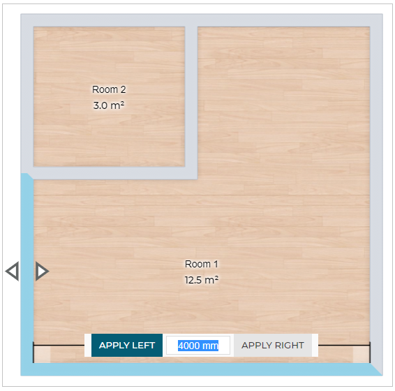
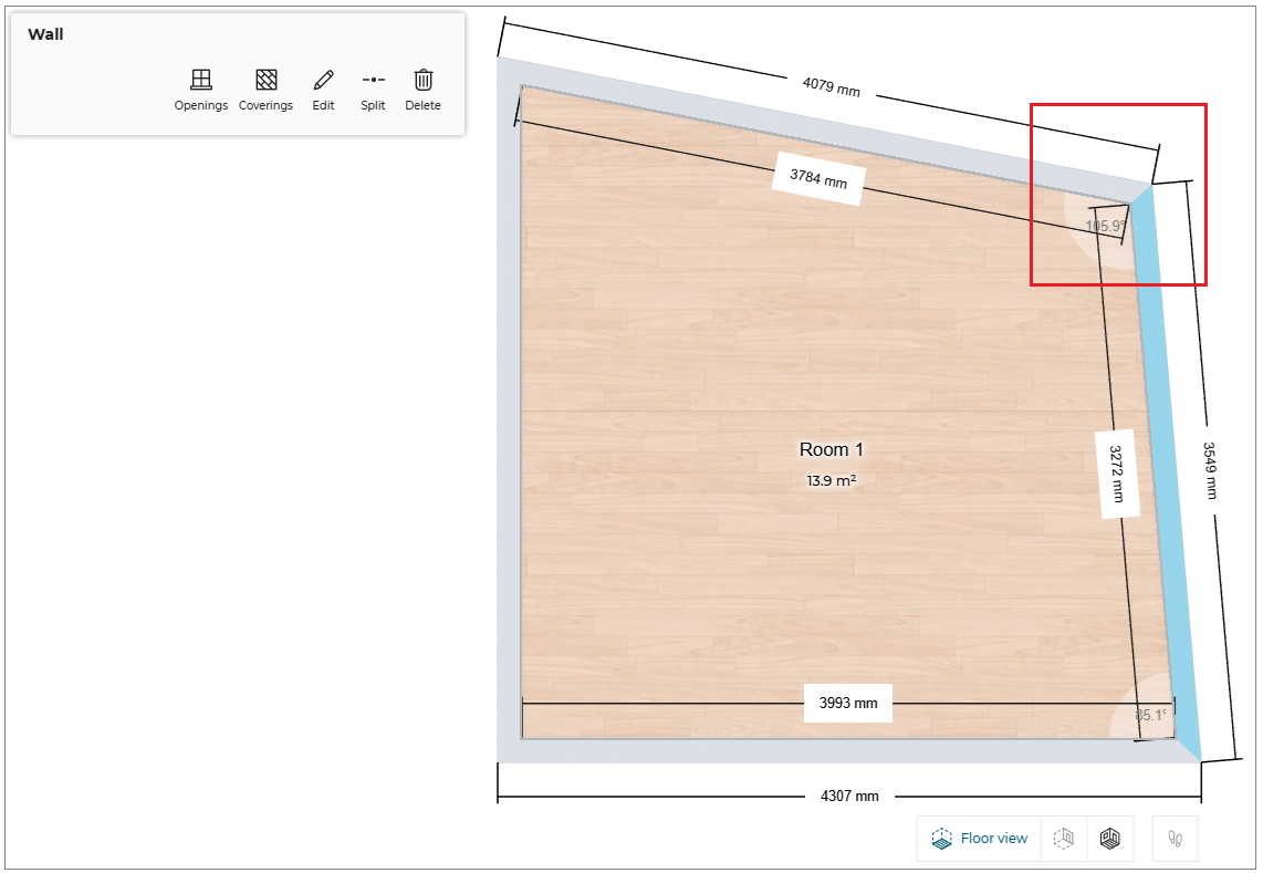
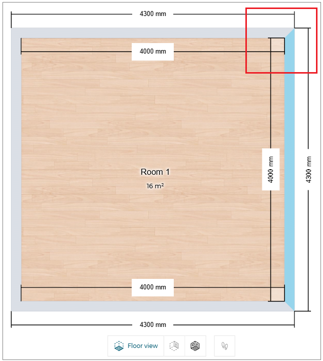
Modifying the Wall Dimension
The dimensions of the walls can be modified by dragging the wall or by specifying the required dimension.
To modify the dimension of the wall in the planner:
- Select the wall, click the dimension of the wall, as shown below:
-
Modify the dimension value of the wall, click APPLY LEFT or APPLY RIGHT button as required.
Selecting the appropriate button changes the length of the wall in the respective direction.
If you press the Enter key, by default the change in the dimension is applied in the direction of the button highlighted in blue color. In the above image, it is APPLY LEFT. -
If you select the vertical wall/ slanting wall, the APPLY ABOVE and APPLY BELOW appears to modify the wall dimension.
If the two adjacent walls of the room are joint at a perpendicular angle (i.e. 90 degree), then a square symbol is displayed, as shown above.
For non-perpendicular angles, the angle value is displayed.
Adding Sloped Ceilings
You can add the sloped ceiling on the wall using one of the following methods:
- Click the Manage sloped ceilings option, the Add sloped ceiling editor appears, as shown below:
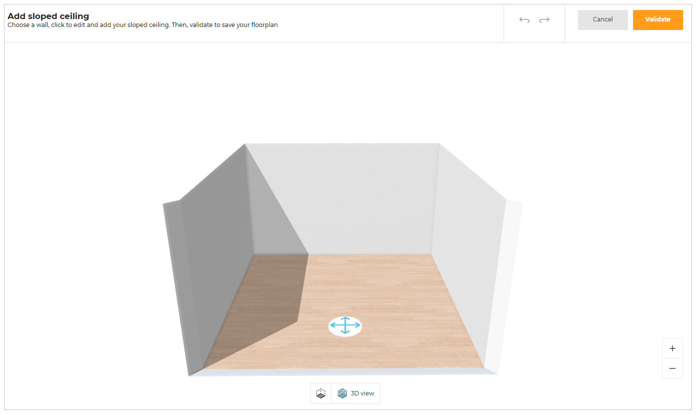
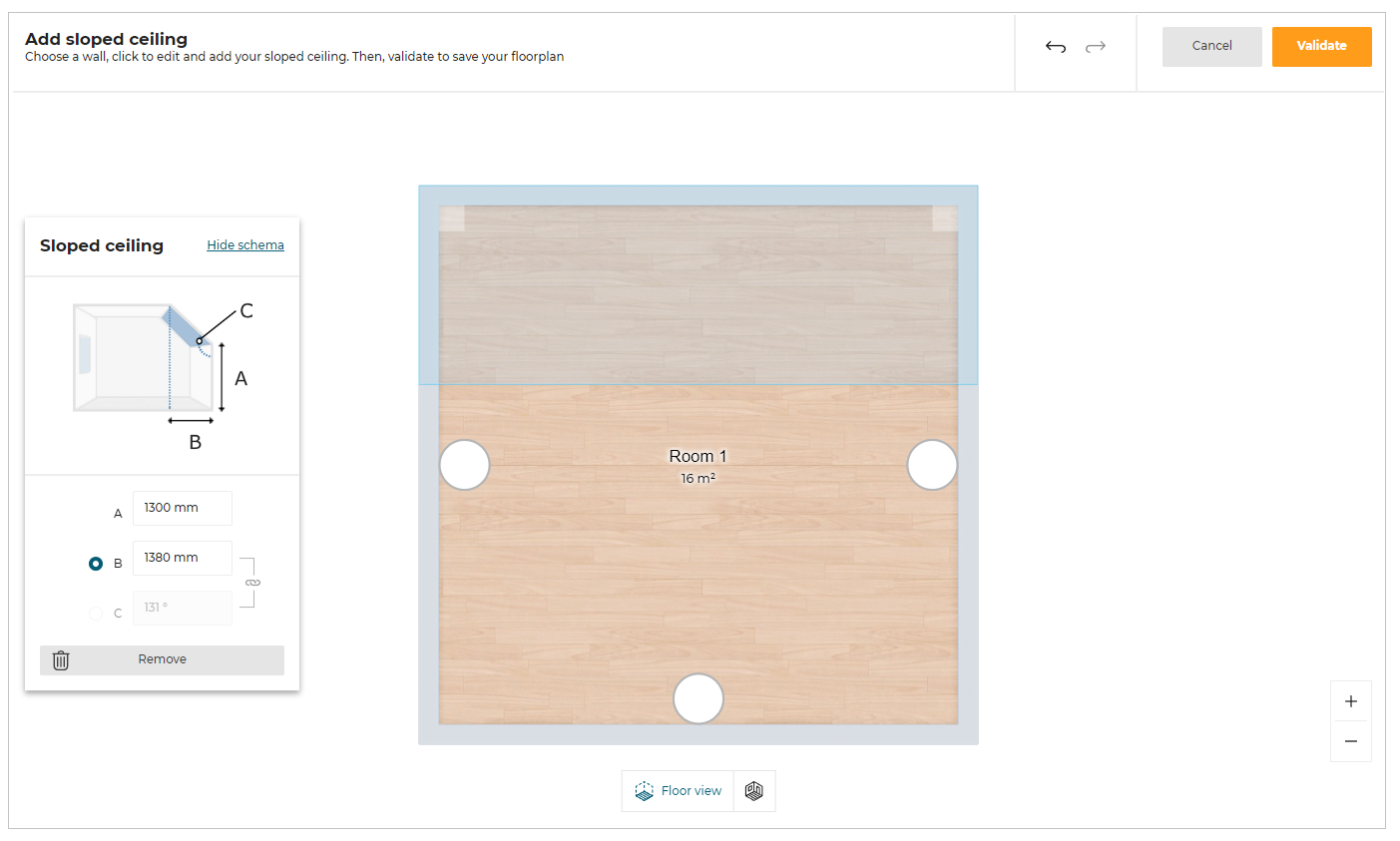
Select the wall on which the sloped ceiling needs to be added, sloped ceiling options with schema window appears, as shown below:
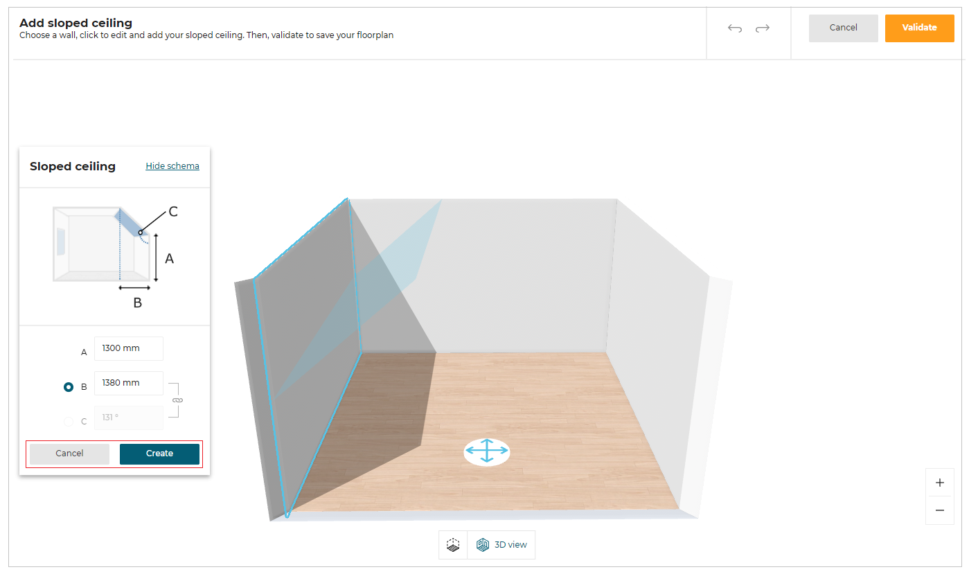
Enter the required dimension values of the sloped ceiling, click the Create button.
To close the sloped ceiling with the schema window, click the Cancel button.
- Select the wall in 2D view and in Edit options, click the Add button from the Sloped ceiling option.
The Add sloped ceiling editor appears, as shown below:
Enter the required dimension values, click Validate to add the sloped ceiling.
For more precisions, A, B and C attributes are explained below:
- A represents the value of the height of the wall from the floor, where the sloped ceiling is located.
- B represents the value of the distance between the start of the sloped ceiling and the smallest height of the wall. (see image above).
- C represents the value of the angle of the sloped ceiling.
The user needs to choose between the B and C attributes to set the correct dimensions of the sloped ceiling.
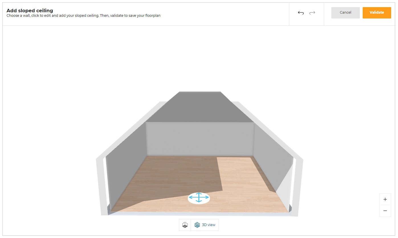
Multiple sloped ceilings can be created, as shown below:
Managing Sloped Ceilings
To modify or delete the sloped ceiling, select the sloped ceiling wall and in the Edit options, click the Edit button from the Sloped ceiling option.
The Sloped ceiling options appears, as shown below:
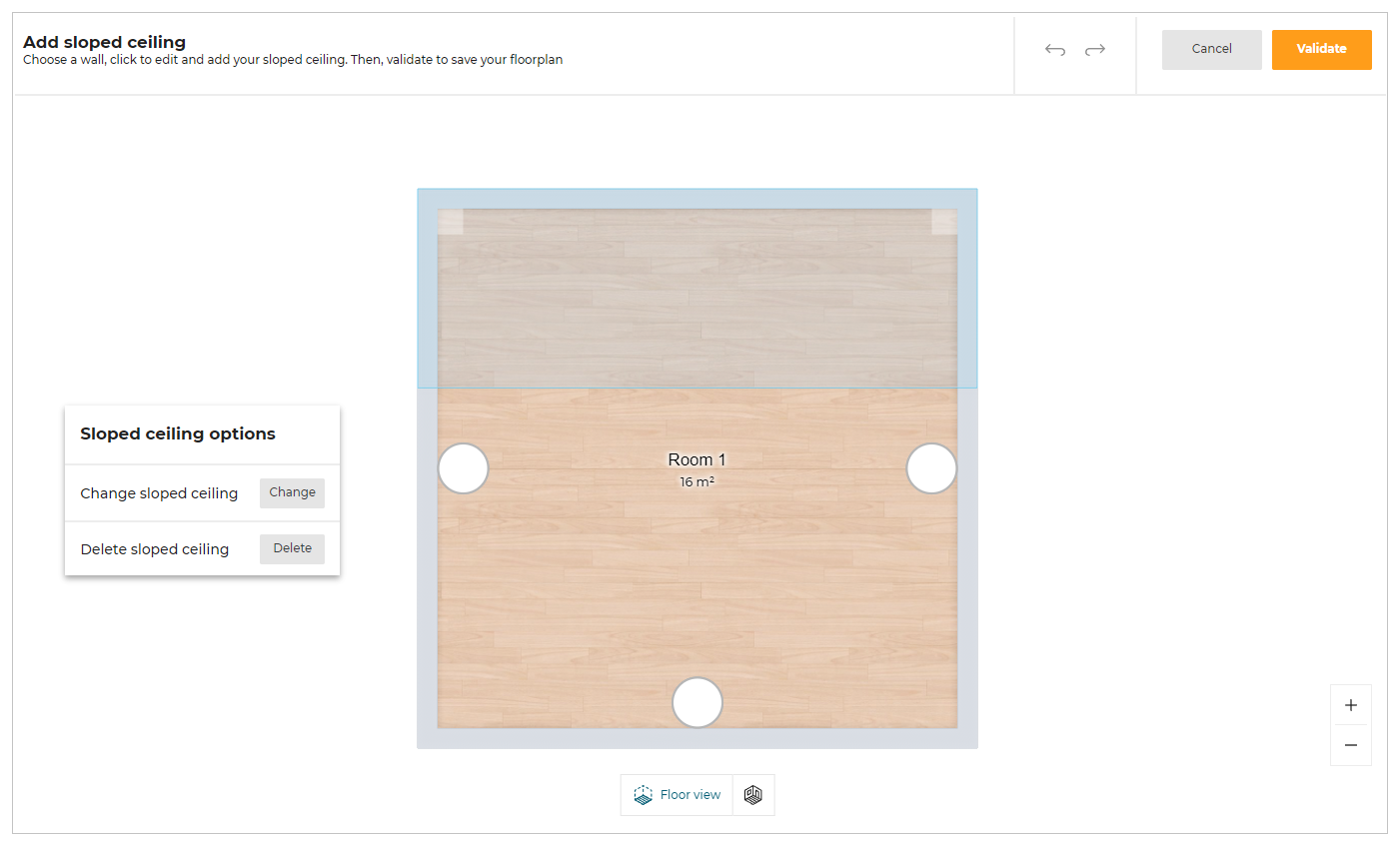
To modify the sloped ceiling, click the Change button.
Sloped ceiling options with the schema appears.
To delete the sloped ceiling, click the Delete button.
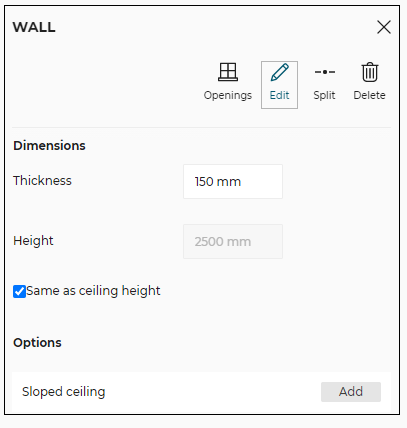
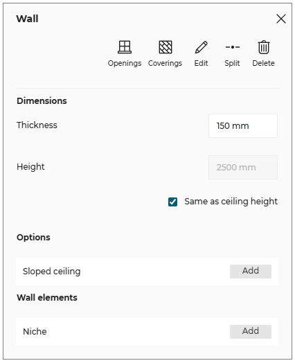
Editing Walls
Select the wall in 2D view.
The toolbar appears, as shown below:

| Option | Function |
|---|---|
Openings | Opens the catalog to add openings (Doors / Windows etc) to the selected wall. |
Edit | Lists editing options. |
Split | Splits the wall into two halves. |
Delete | Deletes the wall. |
The Wall editing options are as follows:
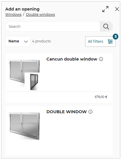
- Openings:
Click the Openings option, the catalog to add a product (Doors/ Windows, etc) appears, shown below:
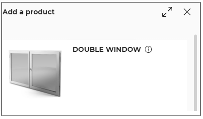
Select the product from the catalog to add it to the selected wall.
This list shows all the products of the openings category like Doors, Windows, and Roof Windows.
- Edit:
Click the Edit option, the options to modify the dimensions of the wall appears, as shown below:
Editing Room Separations
Click the Room Separator option.
The toolbar appears, as shown below:

| Option | Function |
|---|---|
 | Splits the room separator into two halves. |
| Deletes the room separator. |
Openings
This section explains the steps to add the openings (like Door, Window, and Roof window) to the room in the floorplan.
Adding Door / Window/ Roof Window
- Click the
 icon, the list of categories & sub-categories of openings is displayed, as shown below:

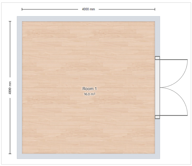
You can add a door/window or roof window by clicking the desired category.
For example, click the Double windows.
The list of double windows appears, as shown below:
Select the Double window from the catalog, the window is added to the wall, as shown below:
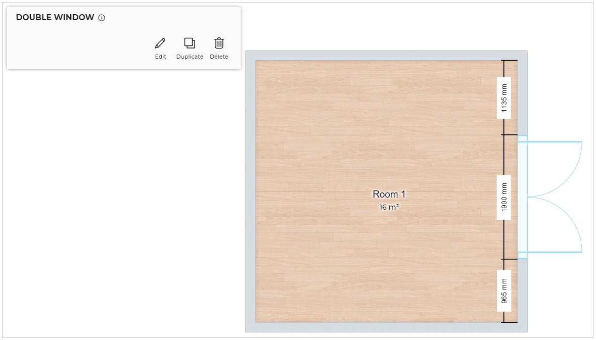
You can move the window to the desired position by dragging it or by editing the measurement that is displayed after selecting it, as shown below:
Similarly, you can add other types of openings like different types of doors, windows, or roof windows.
- The openings width can also be modified by selecting the product and editing the dimensions.
- You can also add the Openings to the room by drag and drop them from the catalog.
- Roof Windows can be added only on the sloped ceiling.
- By default, the distance between the outer wall and the roof window is 200mm.
- Whenever a sloped ceiling is full of roof windows or if the breadth of the sloped ceiling is less than the roof window, and does not have enough space to correctly position the roof windows No space available pop-up appears.
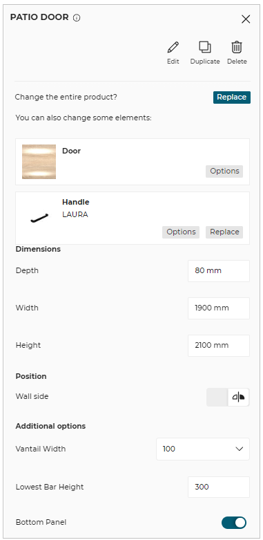
Edit Door / Window Properties
You can Edit door/windows in 2D/3D view.
- Click the door/window to open the Edit toolbar in 2D view, as shown below:

To edit the properties of window/door:
Click the Edit option, the properties panel appears, as shown below:
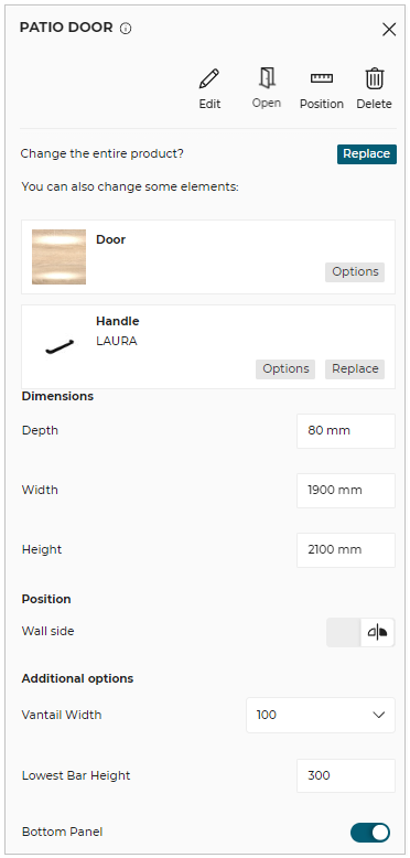
- Click the door/window to open the Edit toolbar in 3D view, as shown below:

To edit the properties of window/door:
Click the Edit option, the properties panel appears, as shown below:
| Option | Function |
|---|---|
 Edit | Lists editing options. |
Duplicate | Duplicates the selected opening and adds it to the room wall. |
Open | Open/Close the openings. |
Position | Moves the opening to the desired position. |
Delete | Deletes the selected opening. |
Information | Shows dimension information about the product. |
Options: Shows the options available for the opening selected.
Replace: You can replace the product/material using this button.
Dimensions: The width, height of the window can be edited.
Position: Height from the floor, wall side (opening of window-inner/outer side), can be edited.
Additional options: For bay products, you can add additional dimension parameters according to your needs.
- The option available in the edit properties window can change depending on the type of opening selected.
- You cannot duplicate the door/window in 3D View.
- You can open/close the openings in 3D view only.
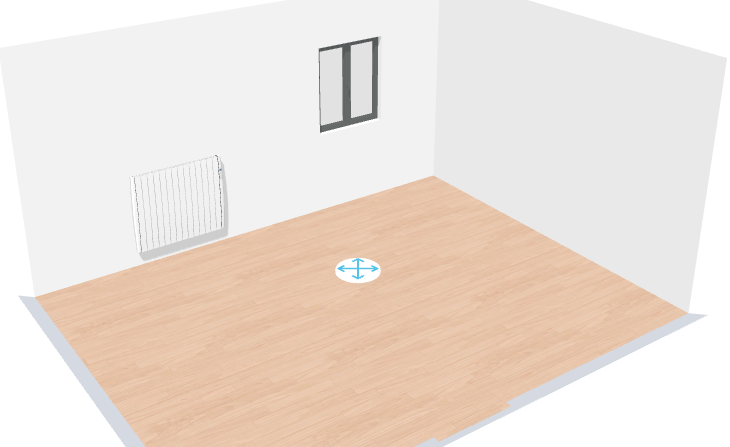
Room Objects
Adding Room Objects
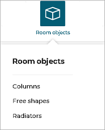
Click the Room objects option from the toolbar, the available room object categories appears, as shown below:
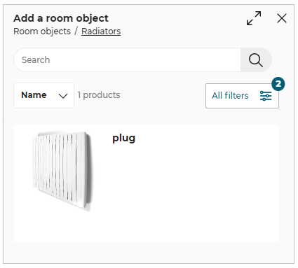
Click the Radiators option to display the list of radiators in the catalog, as shown below:
You can add a product in the room using one of the following methods.
- Click the product thumbnail from the catalog to add it to the room.
- Drag and drop the room object to add it in the room.
The room object is added to the kitchen, as shown below:
Editing Room objects
To edit the room object, select the object, the editing options are displayed.

Edit properties for radiator are:

- Multiple room objects can be selected to perform Duplicate, Position & Delete operations.
- To select multiple room objects, press the Ctrl key from the keyboard while selecting the objects.
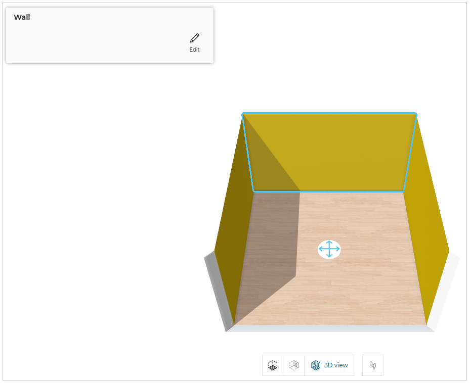
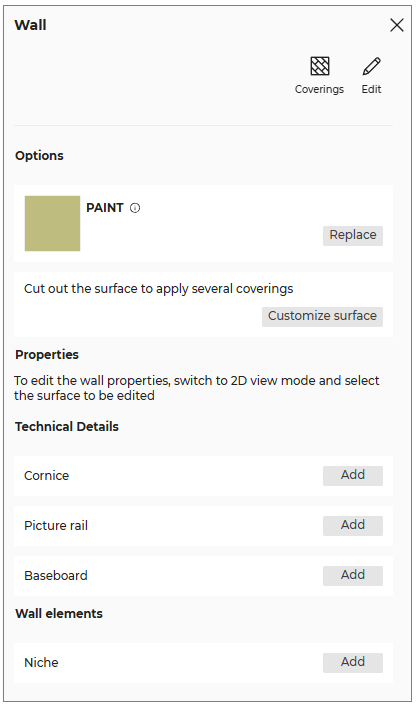
Wall Mouldings
Adding Wall Moulding
You can add the mouldings to the wall.
- Select the wall on which you want to add the moulding, as shown below:
- Click the Edit button, the different types of moulding options are displayed, as shown below:
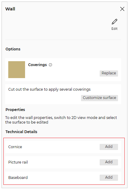
You can add Cornice, Picture rail, and Baseboard type of mouldings.
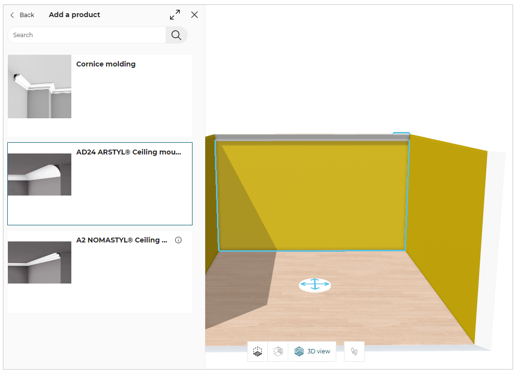
Cornice
You can add the cornice moulding to the wall.
- Click the Add button of Cornice option, and the catalog of cornice moulding are displayed, as shown below:
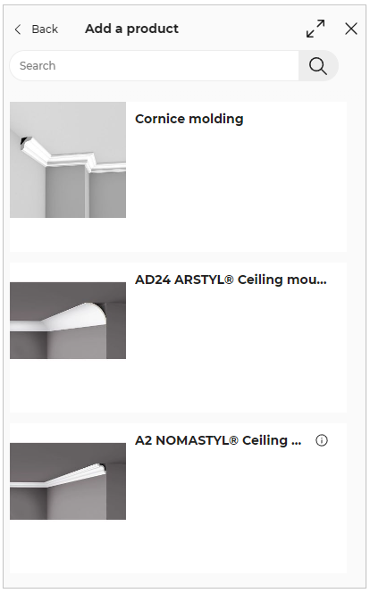
- Select the required cornice moulding from the catalog, the applied moulding is displayed, as shown below:
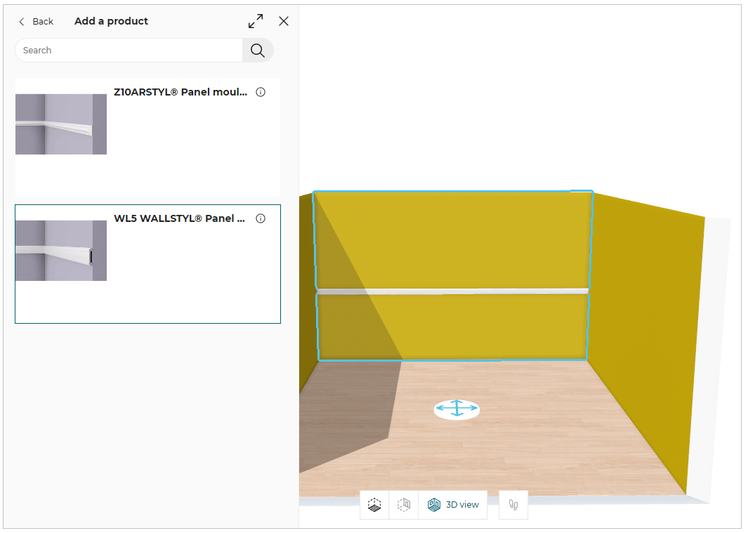
Picture rail
You can add the picture rail moulding to the wall.
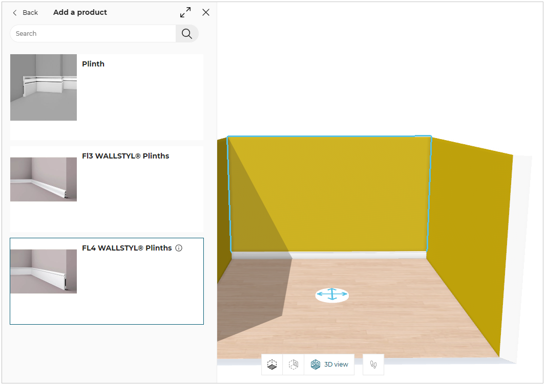
- Click the Add button of Picture rail option, and the catalog of picture rail moulding are displayed, as shown below:
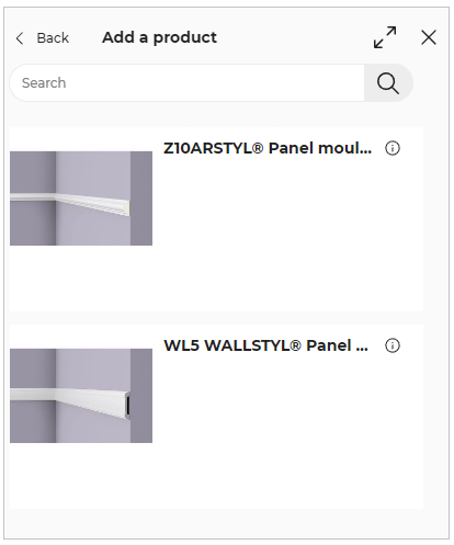
- Select the required picture rail moulding from the catalog, the applied moulding is displayed, as shown below:
Baseboard
You can add the baseboard moulding to the wall.
- Click the Add button of Baseboard option, and the catalog of baseboard moulding are displayed, as shown below:
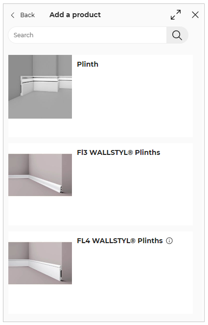
- Select the required picture rail moulding from the catalog, the applied moulding is displayed, as shown below:
Edit Wall Moulding
- Select the wall and click the Options button, as shown below:
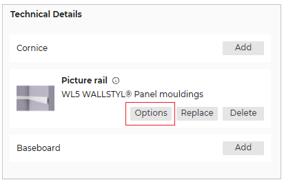
- The Options panel is displayed, as shown below:

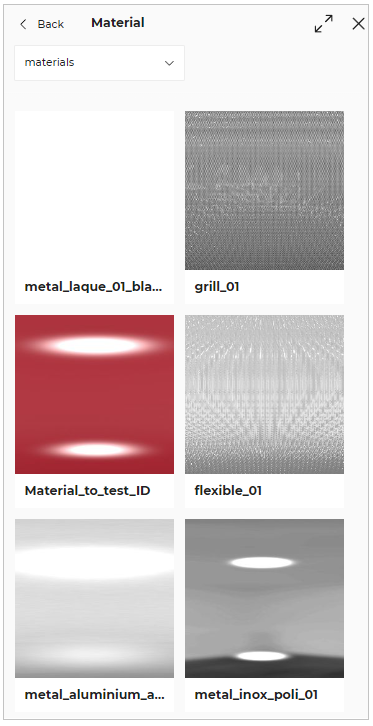
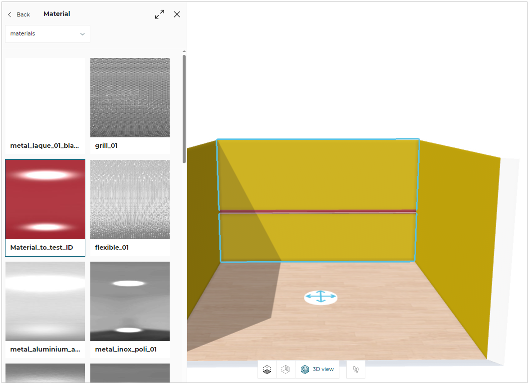
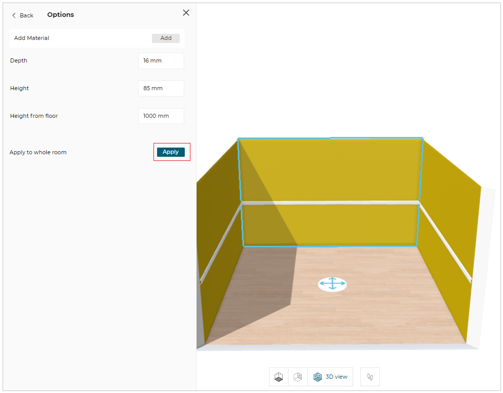
- Click the Add button of the Add Material option to apply the material to the moulding.
The material catalog is displayed, as shown below:
- The applied material to the moulding is displayed, as shown below:
You can edit/modify the dimensions of the mouldings, as shown below:

To apply the moulding to the whole room:
Click the Apply button of the Apply to whole room.
The applied moulding is displayed, as shown below:
Replace Wall Moulding
- Click the Replace button to replace the wall moulding.
The replaceable moulding catalog is displayed, as shown below:
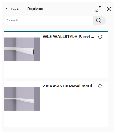
- Select the moulding from the catalog to replace the wall moulding.
Delete Wall Moulding
- Click the Delete button to delete the wall moulding.
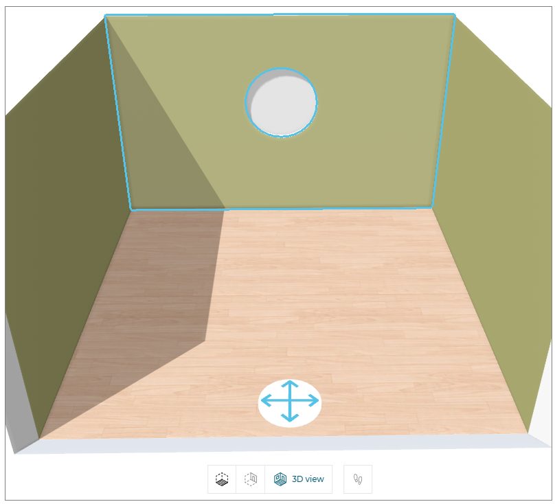
Niche
You can add a Niche into a wall to create a recessed space for fixtures, decorative items, kitchen accessories, etc in 2D/3D view.
-
Select the wall in the 2D/3D view.
-
Click the Edit button, the Wall options are displayed, as shown below:
- Click the Add button of the Niche option, the niche products catalog is displayed, as shown below:
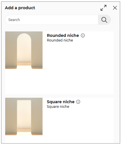
- Select the required niche product from the catalog, the applied niche is displayed, as shown below:
Replace Niche
- Click the Replace button, to replace the niche product.
The Replace niche catalog is displayed, as shown below:
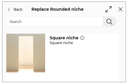
- Select the product from the catalog to replace the niche product.
Edit Niche Parameters (2D & 3D)
You can edit the niche parameters in 2D and 3D views.
- Select the niche in the 2D/3D view, the property window is displayed, as shown below:

- Click the Edit button, the niche parameters are displayed, as shown below:
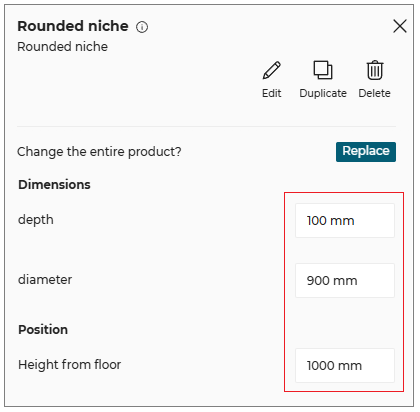
- Select the dimension value of the Niche product, and modify the required dimension.
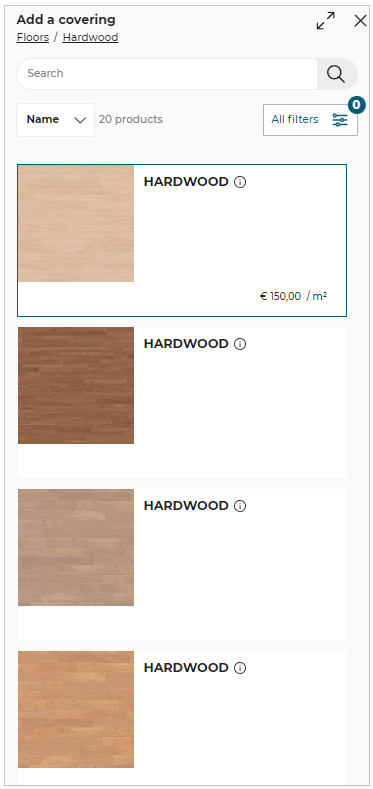
Coverings
⚙️ Set up: Set Up Coverings 🔗 and CoveringRule 🔗
For more information, please refer Bill of Material Reference🔗
⚙️ Set up: Application distribution parameter sortBy🔗 and filters🔗
This section explains the steps to add coverings on the walls, floors and free shapes.
You can add the coverings in 2D/3D view.
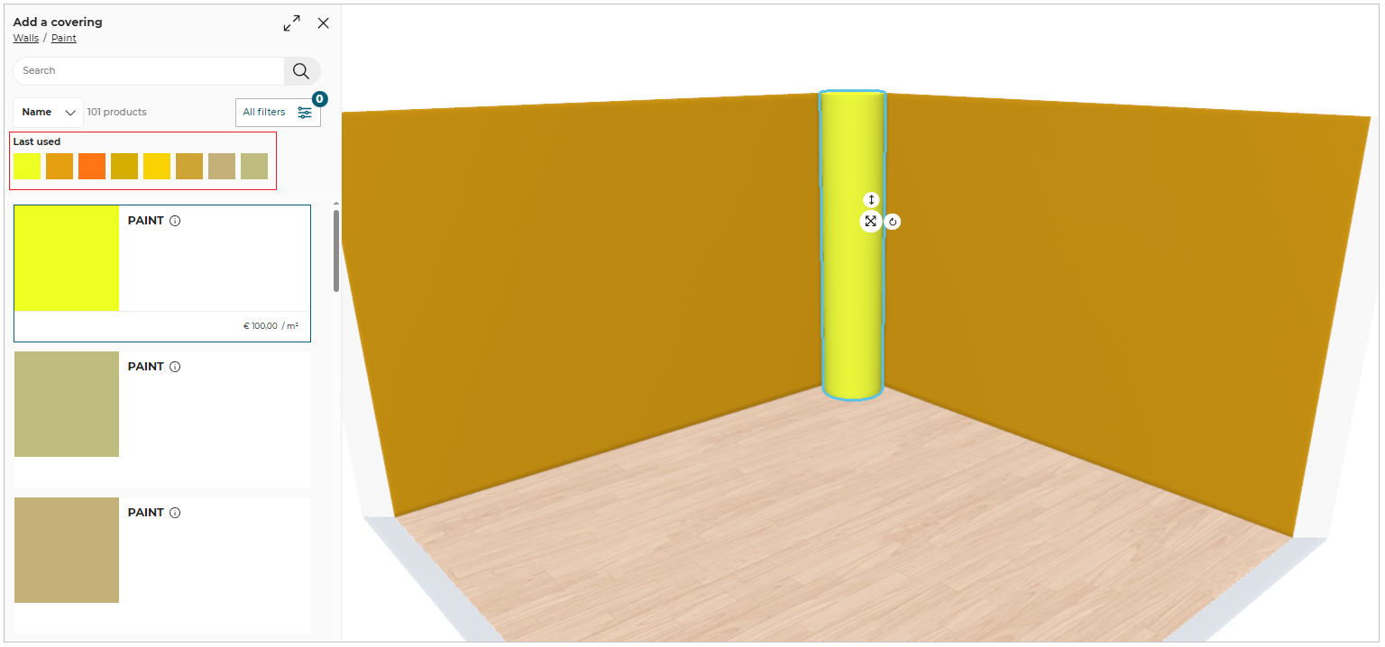
- Select the wall in the 2D view, the property window is displayed, as shown below:

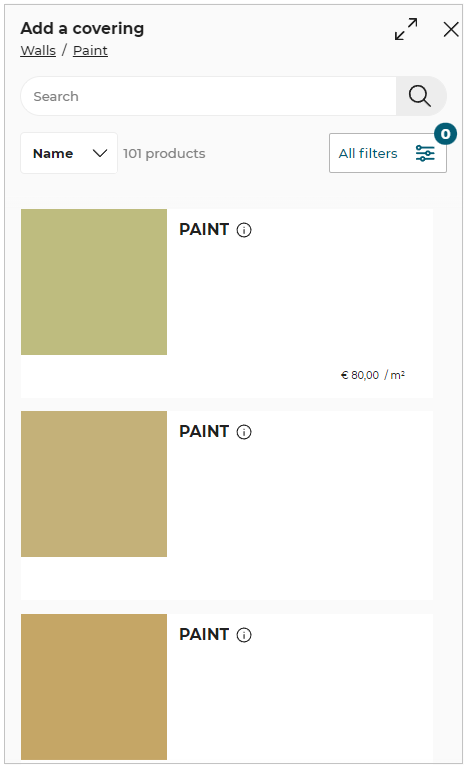
Click the Coverings option from the property window and select the required material from the catalog displayed, as shown below:
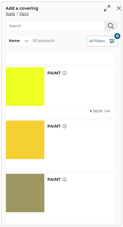
Select the option to sort the material, as shown below:
You can sort the materials using:
- Name.
- Product Rank.
- Start Date.

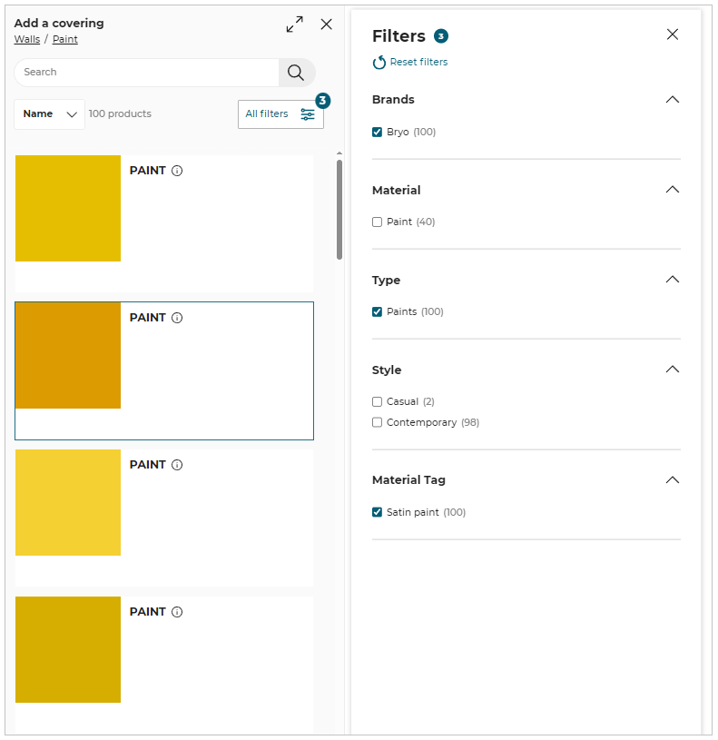
Click the All filters option, to filter the materials, as shown below:
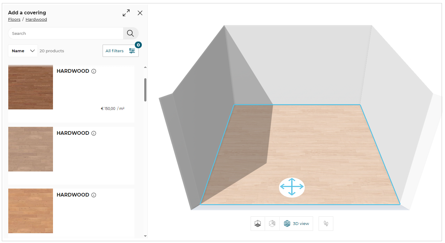
You can add floor coverings by selecting the room floor. The property window is displayed, as shown below:

Click the Coverings option from the property window and select the required material from the catalog displayed, as shown below:
- Select the wall in the 3D view, the paint catalog is displayed, as shown below:
You can add floor coverings by selecting the room floor. The coverings catalog is displayed, as shown below:
- To add coverings on free shapes:
Select the product, the property window is displayed, as shown below:

Click the Coverings option, to open the coverings catalog.
The coverings can be added by using one of the following methods:
- Apply to all option applies covering to all walls and free shapes.
- Apply option applies covering to selected floor, wall or free shapes.

- Last used material
The materials which are applied to the wall, floor or free shapes are displayed in the Last used list, as shown below:
The last used material can be applied by selecting the wall, floor or free shape and clicking the required material from the list.
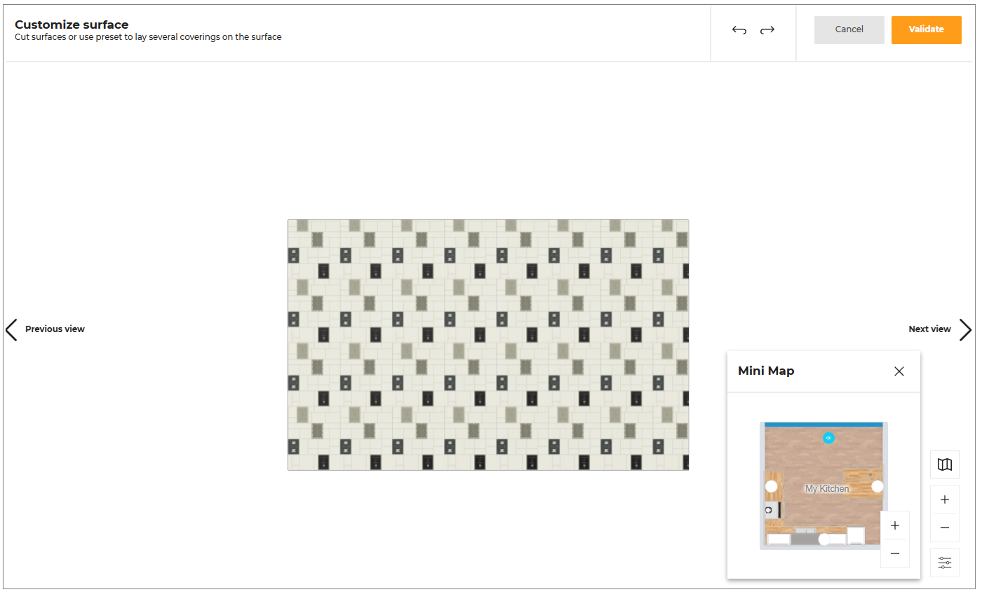
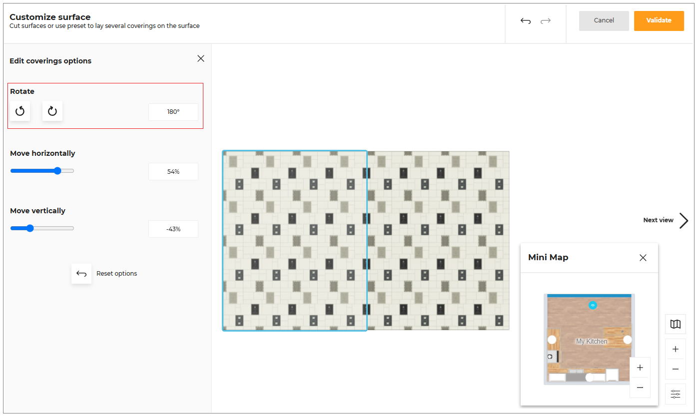
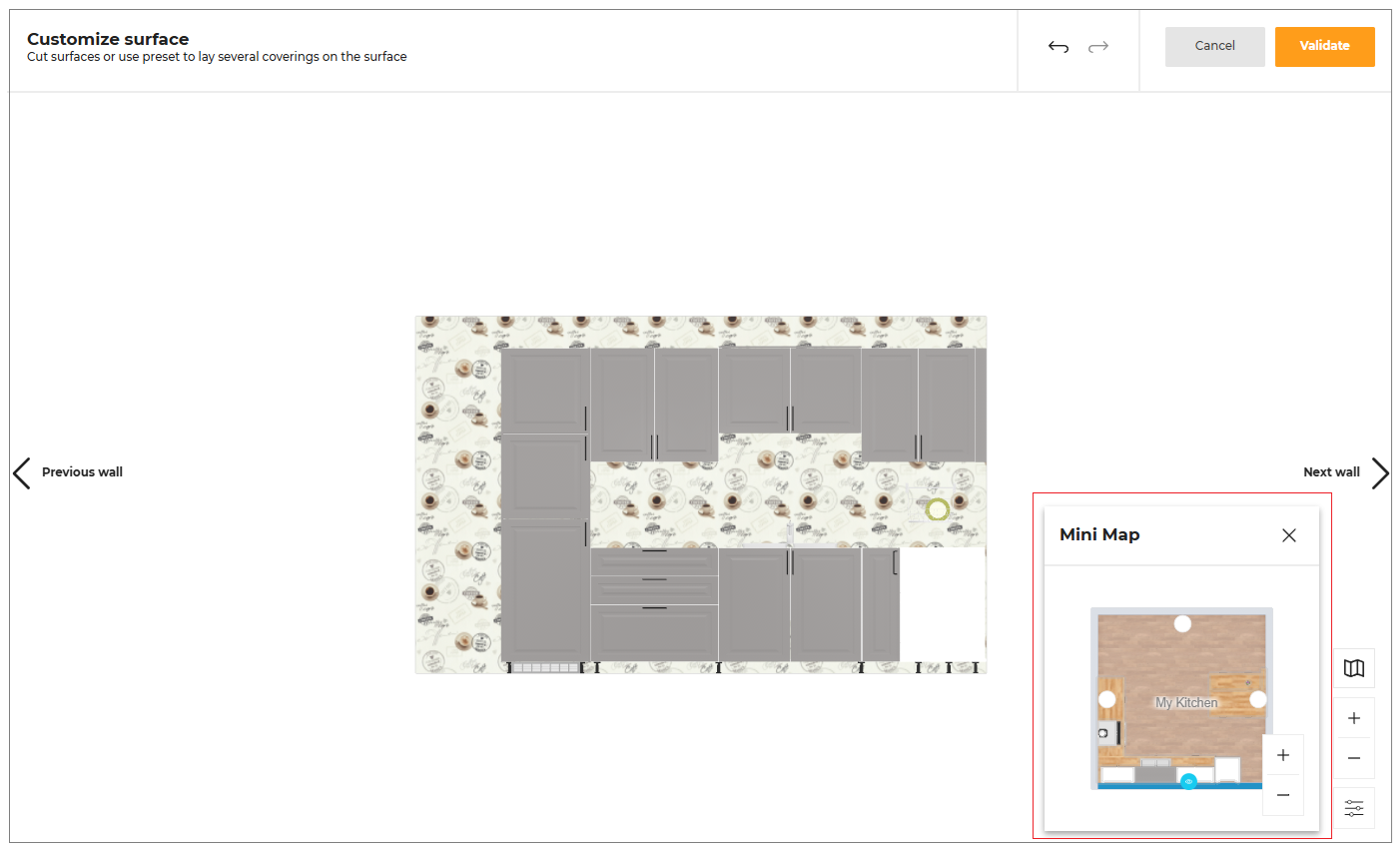
Customize Surface
You can customize the covering surface.
- Select the wall in the 3D view, the edit wall window is displayed, as shown below:

- Select the wall in the 2D view, the property window is displayed, as shown below:

- In the 2D view click the Coverings options, the edit wall window is displayed, as shown below:
- Click the Edit button, the customize surface option is displayed, as shown below:
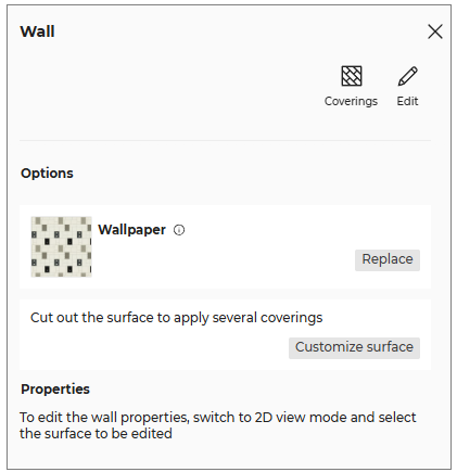
- Click the Customize surface button, the Customize surface window is displayed, as shown below:
Edit Surface
- Select the surface, the Options window is displayed, as shown below:
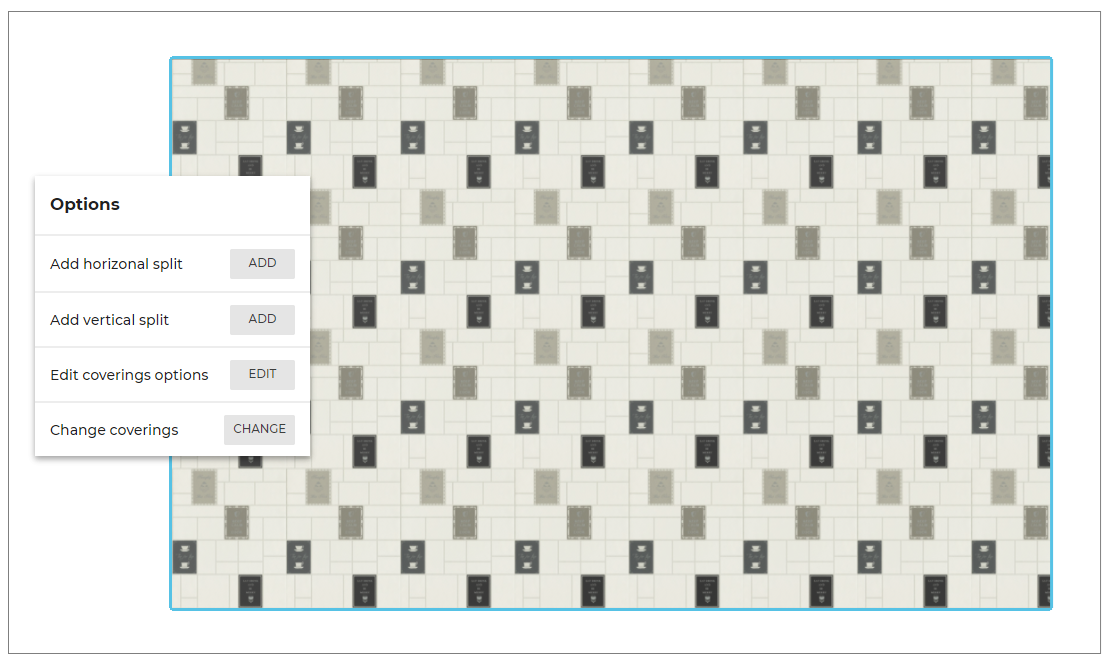
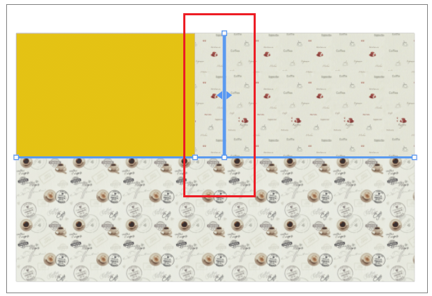
Split
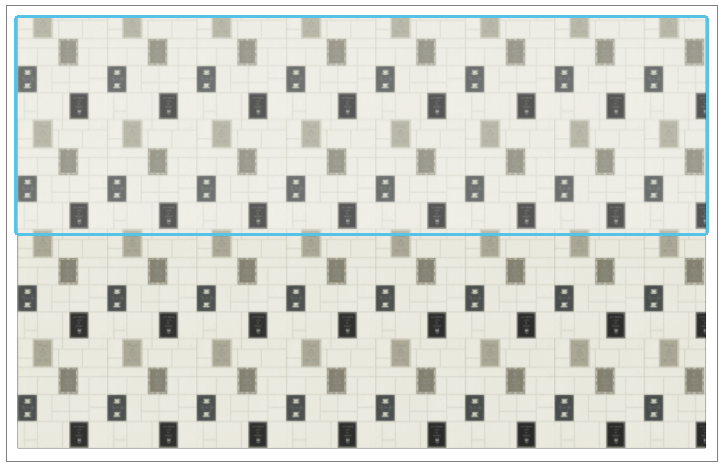
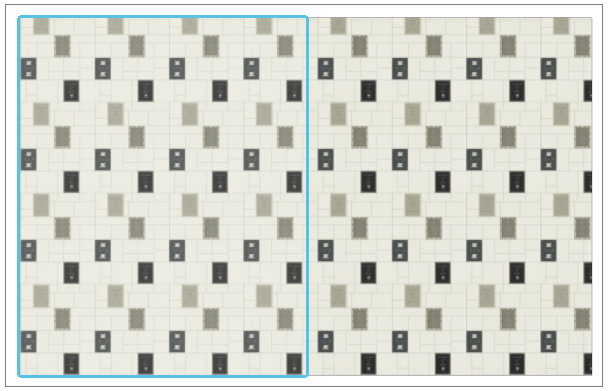
You can split the covering surface in horizontal and vertical direction.
To split the surface in horizontal direction:
- Click the ADD button of the Add horizontal split option.
The horizontal split surface is displayed, as shown below:
- Click the ADD button of the Add vertical split option.
The vertical split surface is displayed, as shown below:
You can drag and drop to adjust the size and position of the horizontal and vertical splits, as shown below:
Edit coverings options
You can edit the coverings.
To edit the coverings surface:
- Click the EDIT button of the Edit coverings options.
The Edit coverings options panel is displayed, as shown below:
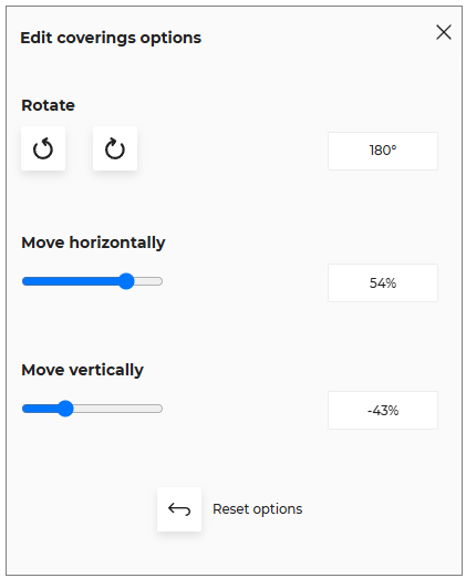
- Click the rotate icon, to rotate the surface in anti clockwise or clockwise direction respectively.
The covering surface is displayed after rotating the surface, as shown below:
Translate Covering Surface
You can move the covering surface in horizontal and vertical direction.
- Click in the input box to enter the value, as shown below:

-
You can also toggle left/right side to move the covering surface in horizontal/vertical direction.
-
Click the reset icon, to reset the modified values.
The minimum and maximum value to move the surface horizontally and vertically is -100% and 100% respectively.
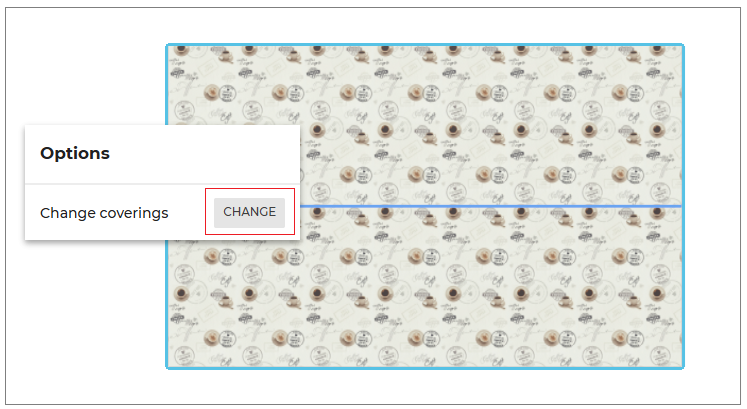
Change coverings
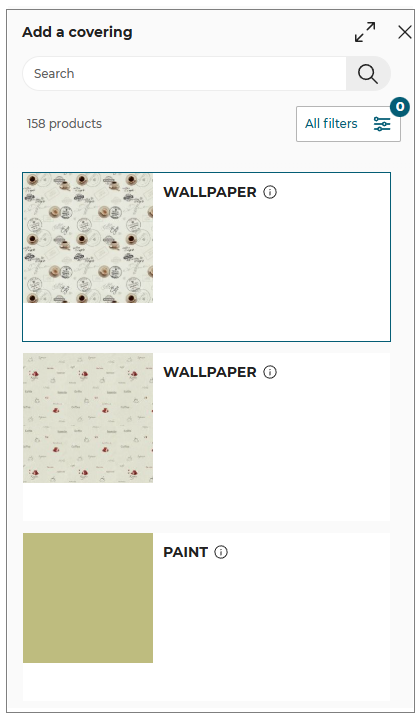
- Click the CHANGE button of the Change coverings option.
The coverings catalog is displayed, as shown below:
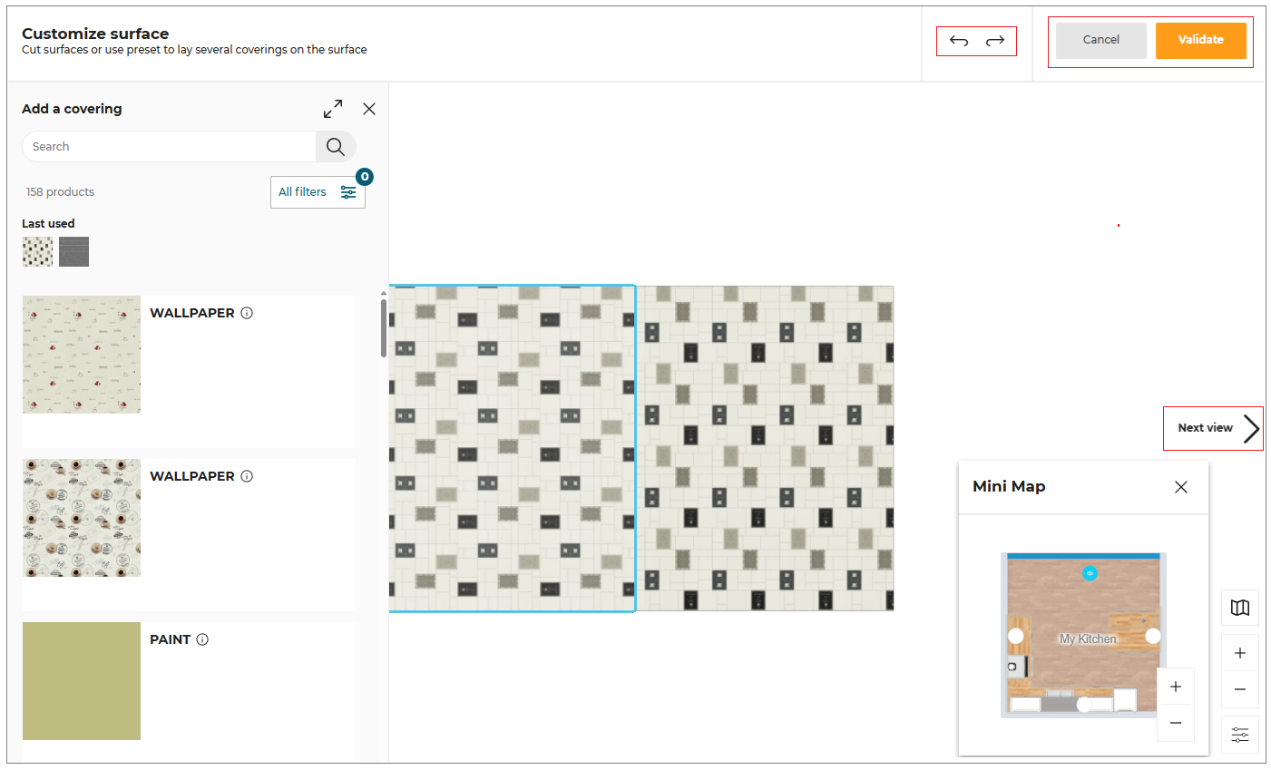
Select the required material from the catalog to apply.
You can select multiple faces and apply or change the covering material to the walls/floors.
- Select the Ctrl button and click the multiple face.
The option to change the material is displayed, as shown below:
- Click the CHANGE button. The covering catalog is displayed, as shown below:
- Select the required material from the catalog to apply.
Undo/Redo
- To undo the previous action, click the
 icon.
icon. - To redo an action, click the
 icon.
icon.
-
Select the Next view/previous view option to preview the covering surfaces.
-
Click the Validate button once the covering surface is customized accordingly.
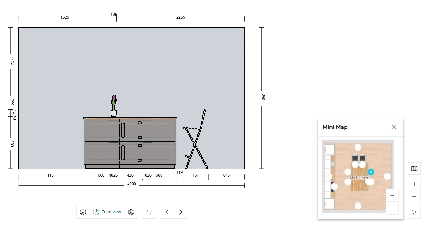
Mini Map
The mini-map feature enhances your design experience by providing a comprehensive overview of your entire project, as shown below:
This tool allows you to easily switch between different walls in the Advanced Decoration layer.
-
Click the Next Wall or Previous Wall option to switch between walls.
-
Click the
 icon to close the mini map.
You can Zoom in or Zoom out the room in the mini map using the mouse scroll wheel.
When designing islands in the Front Elevation view, a virtual plan is created to simulate a physical wall.
You can select the icon corresponding to your island cabinet through the mini-map to go to the Front Elevation view and continue your design, as shown below:
Water Supply
This section explains the steps to select the wall for water supply.
It is not possible to add water supply to room separator.
Click the Water supply option from the toolbar.
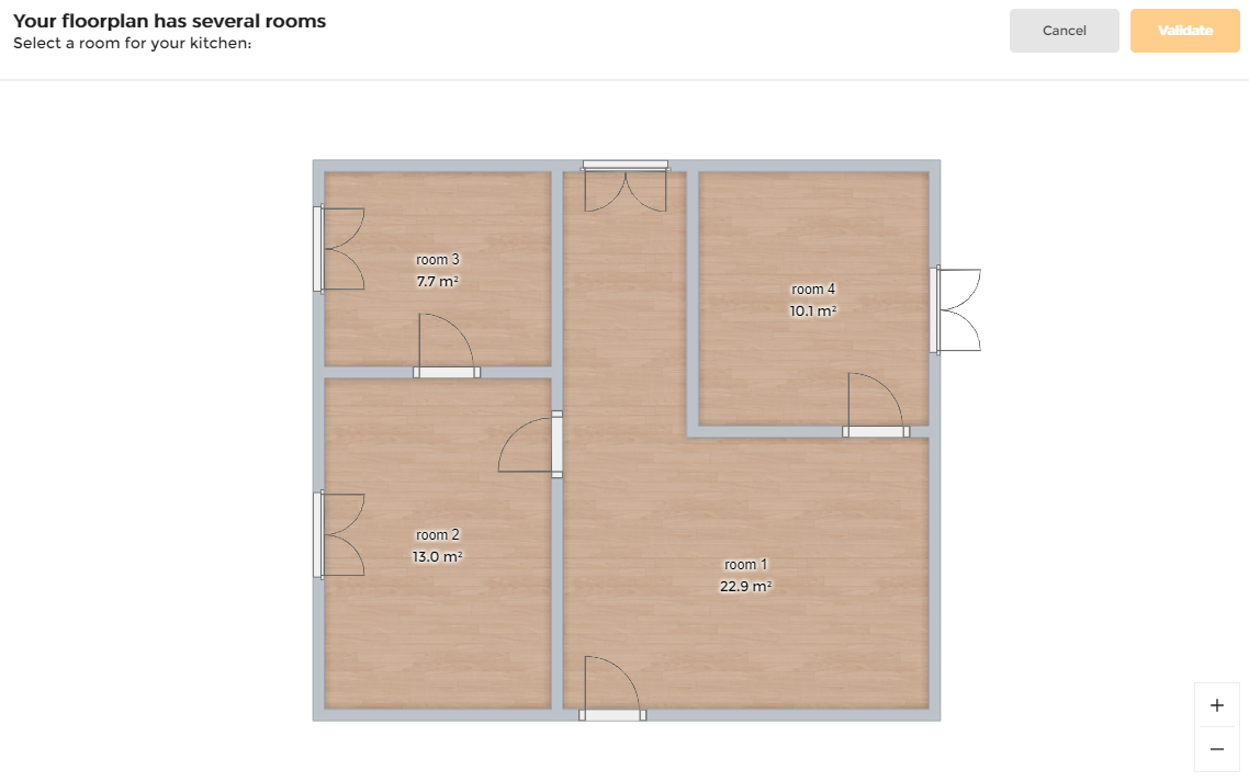
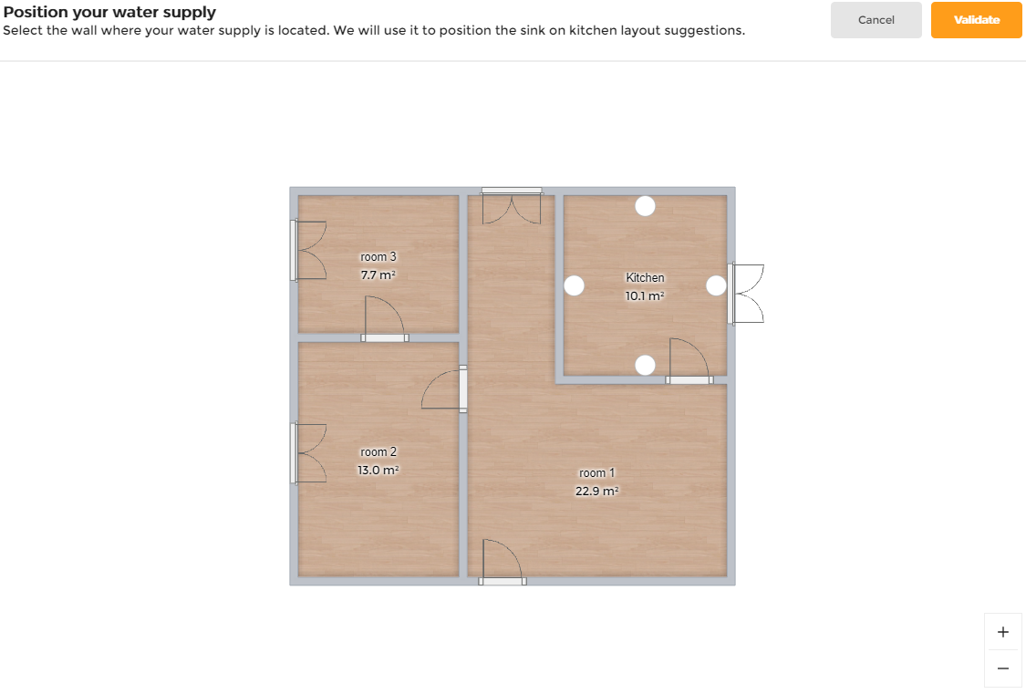
Case 1. If there are multiple rooms in the floorplan, a message appears to select a room for the kitchen, as shown below:
Select the room for the kitchen.
Case2. If you have single room in your floor plan, Position your water supply message appears, as shown below:
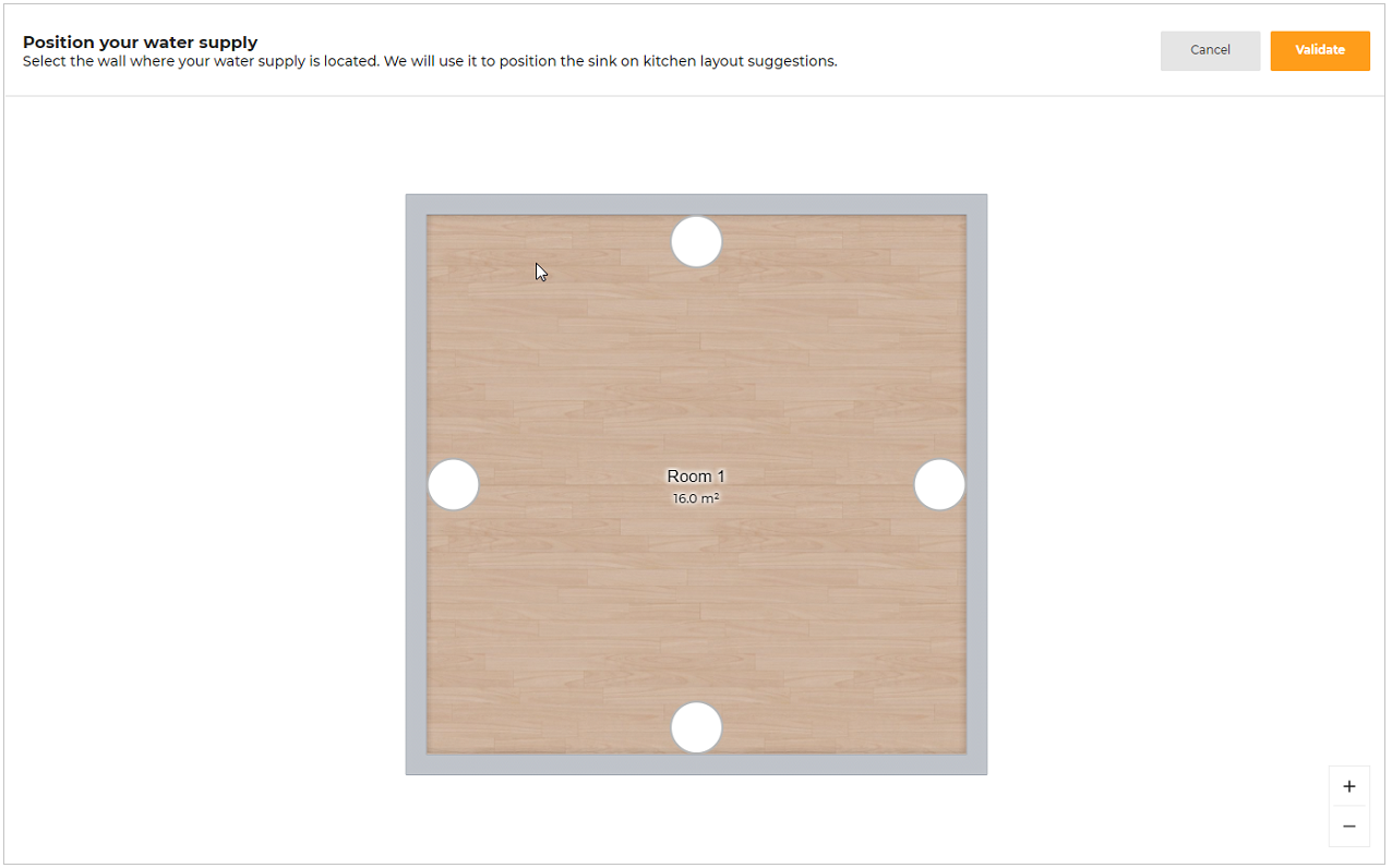
A message appears to select a wall for the water supply.
Click any wall or circle to select wall for water supply.
Selected wall is highlighted as shown below.
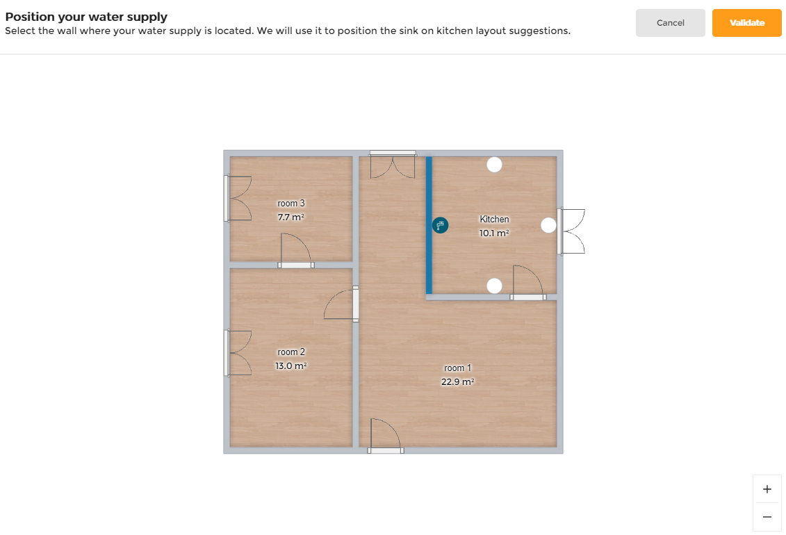
Click Validate to confirm the selection.
If no wall is selected and user clicks Validate, then this popin appears,

If User clicks on Continue, then we proceed with automatic water supply selection.
Ceiling Height
Click the value of ceiling height to modify the room wall height, as shown below:
The minimumm value of the ceiling height should be 1000 mm.

The Water supply option is not displayed in the toolbar, when the Pick a Layout step is removed from the Application by setting
proposalStepparameter asfalsein the Application distribution settings.
Angle Modification
This section describes how you can view and modify the angle between two walls in the floorplan step.
Viewing the Angle
- Click on any wall in the 2D view.
The angle value is displayed, as shown below:
- If the wall is perpendicular (90°), a perpendicular icon appears next to the angle value, as shown below:
Modifying the Angle Value
- Click the angle value twice.
- The UI switches to angle‑edit mode, as shown below:
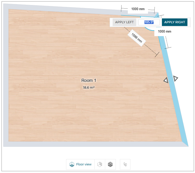
-
Two buttons appear: Apply Left and Apply Right.
- The current angle value is pre‑filled in the input field.
-
Edit the value and press Enter or click the desired Apply button.
- The angle is applied to the selected side (left/right).
Validation & Error Handling
- Pressing Enter stores the new angle and updates the room geometry instantly.
- If the entered value is invalid (e.g.,
36000), the system reverts to the previous valid angle without showing an error message.
Quick Reference
| Action | UI Element | Result |
|---|---|---|
| Click wall | Angle value + optional perpendicular icon | Shows angle |
| Click angle value | “Apply Left / Apply Right” buttons + input | Enters edit mode |
| Press Enter | – | Saves angle (default side based on context) |
| Invalid input | – | Reverts to previous angle, no error popup |
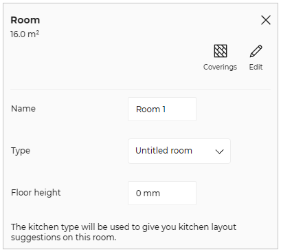
Rename room
You can modify the room, room type, and modify the floor height.
- Click the room floor, the property panel is displayed, as shown below:

- Click the Edit option, the edit panel is displayed, as shown below:
-
Name- Select the room name and modify the required name of the room.
-
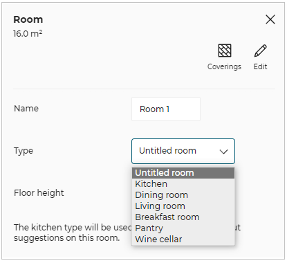
Type- Select the room type from the drop-down menu, as shown below:
- Floor height
To modify the height of the floor in the same room or different rooms:
- Select the value of the floor height and modify the required floor height, and a success message displays, as shown below:

- To check the applied floor height, click the See how it looks from the pop-up message.
The applied floor height is displayed, as shown below: